Introduction
The buck regulator is the basic circuit required to convert a high-voltage, dc input to a lower voltage, dc output. Also known as a step-down regulator, the buck consists of several key power components, including the transistor switch, the free-wheel diode, and the output inductor and capacitor. When a buck converter is driven from an AC line in, it is known as an AC/DC buck converter and is typically preceded in the circuit by a full-wave rectifier that converts the ac to an unregulated dc that is input into the buck. It is crucial to be able to select the major components of the discrete buck in order to deliver the specified, regulated output voltage reliably. The voltage regulation is typically handled by an IC controller, such as the LM2595, which must be properly applied by the designer. Before beginning your Lab, download your Lab cover page here (Links to an external site.)Links to an external site.
Components for the experiment
- DC Power Supply
- LM 2595 Regulator
- Zener diode (1N5921B)
- Capacitor 220micro farads
- Resistor 12 ohms
- Multimeter.
Set-up and Procedure.
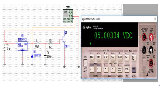
The circuit diagram for the experiment was set as below;
15v DC Power was supplied to the circuit through LM 2595. The output was fed into a 1 kilo ohm resistor and then to the base of a transistor.
STEP 1
From the data given
Vin = 15V
R1= 12 ohms
C1= 68 microfarads
Vout = 5.00304 volts (as indicated in the simulation above).
Therefore the current can be obtained using the following formula.
Current I = . . . . . . . . . . . . . . . . . . . . . . . . . . . . . . . . . . . . . . . . . . . . . . . . . . . . . . . . . . . . . . . . .1
Current I =
Hence current I = 0.41692 A
And the Power Supplied to IC can be obtained using the below formula,
Power Supplied to IC= V×I . . . . . . . . . . . . . . . . . . . . . . . . . . . . . . . . . . . . . . . . . . . . . . . . . . . . . . 2
Power Supplied to IC = V×I
Power Supplied to IC = 15×0.41692
Power Supplied to IC = 6.2538 watts
While the power dissipated, P is given by the following equation;
Power dissipated, P= I2R . . . . . . . . . . . . . . . . . . . . . . . . . . . . . . . . . . . . . . . . . . . . . . . . . . . . . . . . 3
Power dissipated, P= 0.416922×12
Power dissipated = 2.0856 watts
And the junction temperature is obtained using the following equation
Jt = Ta +( Ra×Pd) . . . . . . . . . . . . . . . . . . . . . . . . . . . . . . . . . . . . . . . . . . . . . . . . . . . . . . . . . . . . .4
Where Jt is the junction temperature, Ta is the ambient temperature and Pd is the power dissipated by IC.
Hence Jt = 50 + (12× 2.0856)
Junction temperature = 50+ 34.272
Junction temperature = 84.2720C
The duty cycle from the above
STEP 2. QUESTIONS AND DISCUSSION.
Question 1. Operation of LM2595.
The chip LM2595 is grouped as a Regulator (Voltage regulator). It has an integrated circuit which offers an important function for instant step-down (buck). The regulator is able to drive a load rated 1 A. The chip incorporates an internal fixed frequency oscillator and it functions at a switching frequency of about 150 KHz. When a given voltage is fed into the regulator, the signal is converted again into DC form but with less magnitude. This process is made effective by internal fixed frequency oscillator.
Question 2. Ripple current.
Basically, ripple current is an electrical signal which arises because of incomplete attenuation of the AC sinusoidal signal in a particular power supply. Ripple current increases with an increase in the frequency of oscillation. Ripple current factor is always expressed as a percentage. It is defined by the ratio of RMS (root mean Square) value of the ripple current to the absolute value based on the condition of the output DC voltage. The magnitude of ripple current depends on the load resistor value and the size of the capacitor. The current can hence be reduced by increasing the value of C (Capacitance). Mathematically the ripple