Problem Statement
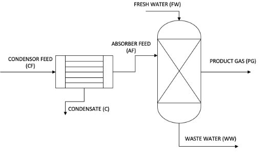
In the final stage of the biomass gasification process, a product is concentrated in a feed water containing 91 %% aqueous vapor, 8.22% hydrogen and 0.18% sulfur dioxide for water removal, before the product is introduced to the absorber (stream CF) to reduce the gas. Sulfur dioxide level in the stream. The process flow diagram is displayed below. The feed gas entering the condenser is filled with 2 bar and aqueous steam. The condenser feed is cooled to 30 ° C and the exit fluid (stream C) is adjusted to evaporate the AF stream. The absorbent was also driven 2 times and at 30 ° C, and 2 times, fresh water was found in the flow FW. Hydrogen is not very dense or dissolved in water, so it can be assumed that there is no hydrogen in stream C or WW.
This is the process of final gasification unit where a gas stream containing water along with sulfur di oxide and hydrogen gas is fed into the condenser to collect the water as a liquid. After that in this cleaning process it is send to the absorber to scrub the sulfur di oxide gas in to the flow of fresh water. There is no hydrogen stream in the waste water as well as in condensate. (Chen E, 2013).
The deliverable task is to calculate the flow rate and the specific enthalpy of the each stream. From this data required to calculate the heat duty of the condenser as well as the absorber.
Assumption
- There is no hydrogen stream in the waste water as well as in condensate.
- The vapor is fully condensed in the condenser
- Specific heat of the water is 4.18 kJ/kmol, Specific heat of the sulfur di oxide is 43.52 kJ/kmol, (Frailie PT, 2013)
Data
| Substance | Phase | Stream | Component Flowrate (kmoli/hr) | Specific Enthalpy(kJ/kmoli) | Temperature(°C) |
| Water | CF | 91.6 | |||
| Sulfur dioxide | CF | 0.18 | |||
| Hydrogen | CF | 8.22 |
Analysis
The governing equation in this problem is,
whereP is the system pressure, yi is vapour mole fraction of component i, xi is liquid mole fraction of component i, and is the equilibrium vapour pressure of water at temperature T. (Chen E, 2013).
Calculation
Basis of calculation:
100 kmol of the feed gas in the feed stream
Water vapor in the feed gas stream = 91.6 kmol
Pressure – 2 bar = 200 kPa
The stream is saturated with water vapor,
At 200 kPa saturated water vapor temperature = 120.21 C
Mole fraction of SO2 in CF = 0.0018
In CF stream,
Water = 91.6 kmol
SO2 = 0.18 kmol
H2 = 8.22 kmol
Let assume in absorber feed (AF) stream, Water present W kmol and SO2 present S kmol,
So in the condensate C stream,
Water present (91.6-W) kmol
And SO2 present (0.18-S) kmol,
Now, as per the equilibrium data,
P.ySO2 = 4.75X xSO2,
Now,
SO,
Again,
P.yH2O = 4.75X(1- xSO2)X P*,
Or,
yH2O = (4.75/2)X(1- xSO2)X 0.00424,
or,
now, m =
so, m=(1-0.42m)x0.0212
so, m = 0.0212/(1+0.42×0.0212) = 0.021
m =
from this we get,
S = 0.17+0.021W,
So,
Or, W= 3.8 kmol,
So, S = 0.17+0.0021×3.8 = 0.176 kmol,
So, in condensate stream,
SO2 = 0.18-0.176= 0.004 kmol,
Water = 91.6-3.8= 87.8kmol,
Now, in AF,
YSO2 = 0.176/(0.176+8.22) = 0.02,
XSO2 = 0.02X2/4.75 = 0.0088,
Let, water flow rate in absorber is W1 kmol,
So, W1x0.0088 = 0.176,
Or, W1 = 20 kmol
b. Specific enthalpy change
CF
Water =4.18x(120.21 – 0) = 502.48 kJ/kmol
SO2 = 43.52x(120.21 – 0) = 5231.53 kJ/kmol
H2 = 28.5x(120.21 – 0) = 3426 kJ/kmol
In, C stream,
Water = 4.18x(30 – 0) = 125.4 kJ/kmol
SO2 = 43.52x(30 – 0) = 1305.6 kJ/kmol
H2 = 0
In AF stream,
Water = 4.18x(30 – 0) = 125.4 kJ/kmol
SO2 = 43.52x(30 – 0) = 1305.6 kJ/kmol
H2 = 28.5x(30 – 0) = 855 kJ/kmol
In FW stream,
Water = 4.18x(30-0) = 125.4 kJ/kmol
SO2 = 0
H2 = 0
In PG stream
Water = 4.18x(30-0) = 125.4 kJ/kmol
SO2 = 0
H2 = 28.5x(30-0) = 855 kJ/kmol
c. Heat duty of the condenser Q =
(91.6×4.18×120.21+0.18×43.5×120.21+8.22×28.5×120.21)- (87.8×4.18×30+0.004×43.5×30+3.8×4.18×30+0.176×43.51×30+ 8.22 x 28.5 x 30 )
= 75130.24 – 18749.69 = 56380.54 kJ / kmol
d. Heat duty of the absorber =
20 x 4.18 x 30 + 3.8 x 4.18 x 30 + 8.22 x 28.5 x 30
= 10012.62 kJ/hr
| Substance | Phase | Stream | Component Flowrate (kmoli/hr) | Specific Enthalpy | Temperature |
| (kJ/kmoli) | (°C) | ||||
| Water | G | CF | 91.6 | 502.48 | 120.21 |
| Sulfur dioxide | G | CF | 0.18 | 5231.53 | 120.21 |
| Hydrogen | G | CF | 8.22 | 3426 | 120.21 |
| Water | L | C | 87.76708449 | 125.4 | 30 |
| Sulfur dioxide | G | C | 0.003834169 | 1305.6 | 30 |
| Hydrogen | G | C | 0 | 0 | 30 |
| Water | L | AF | 3.832915506 | 125.4 | 30 |
| Sulfur dioxide | G | AF | 0.176165831 | 1305.6 | 30 |
| Hydrogen | G | AF | 8.22 | 855 | 30 |
| Water | L | FW | 20 | 125.4 | 30 |
| Sulfur dioxide | G | FW | 0 | 0 | 30 |
| Hydrogen | G | FW | 0 | 0 | 30 |
| Water | L | WW | 20 | 125.4 | 30 |
| Sulfur dioxide | G | WW | 0.176165831 | 1305.6 | 30 |
| Hydrogen | G | WW | 0 | 0 | 30 |
| Water | L | PG | 3.8 | 125.4 | 30 |
| Sulfur dioxide | G | PG | 0 | 0 | 30 |
| Hydrogen | G | PG | 8.22 | 855 | 30 |
G. To minimize the energy losses from the system one has to run the absorber effectively. The heat duty of the absorber should be zero as it is operated at constant temperature. Also for the condenser the effective heat duty is also reduced for the optimize run of the equipment. (Yin F, 2000).
Interpretation And Reflection
There are many approximation has been done to calculate the flow of each stream. First of all the pressure at 2 bar is not realistic for the smooth running of the absorber. For the efficient absorption of the gas stream the pressure of the absorber should be low.
References
Frailie PT, Madan T, Sherman B, Rochelle GT. Energy performance of advanced stripper configurations. Presented at GHGT-11, Kyoto, Japan, November 18-22, 2012. Energy Procedia, 2013.
Madan T, Van Wagener DH, Chen E, Rochelle GT. Modeling pilot plant results for CO2 stripping using piperazine in a two stage flash. Presented at GHGT-11, Kyoto, Japan, November 18-22, 2012. Energy Procedia, 2013.
Chen E, Madan T, Sachde D, Walters M, Nielsen P, Rochelle GT. Pilot Plant Results with Piperazine. Presented at GHGT-11, Kyoto, Japan, November 18-22, 2012. Energy Procedia, 2013.
Frailie PT, Plaza JM, Van Wagener DH, Rochelle GT. Modeling Piperazine Thermodynamics. Presented at GHGT-10, Amsterdam.Energy Procedia, 2011.
Tsai RE. Mass Transfer Area of Structured Packing. PhD Dissertation, TheUniveristy of Texas at Austin: Austin, 2010.
Yin F, Wang Z, Afacan A, Krishnaswamy N, Chuand KT. Experimental Studies of Liquid Flow Maldistribution in a Random Packed Column. The Canadian Journal of Chemical Engineering2000; 78, 449-457.