The resultant wind force acts at two-third of the length from the tip the blade. Thus, the resultant wind force will be two-thirds of the maximum wind force.
Resultant wind force when a blade is at the lowest points in the rotation cycle around the hub is given as;
Similarly, the resultant wind force when a blade is at its highest points in the rotation cycle around the hub is given as;
Question 2
Distance from section AA to the resultant wind force when a blade is at the lowest point will be;
The same applies to the highest point;
Moment is calculated by the formula (Jai B. Kim, 2013)
Thus, moment resulting from is
Same applies to moment resulting from
Question 3
Maximum flexural stress is given by the formula
Where is the centroidal moment of inertia in (Walker, 2013)
We need to obtain ;
Therefore, we can proceed and calculate the maximum flexural stress.
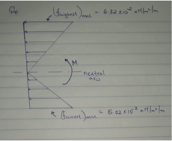
For the lowest point,
For the highest point,
Question 4
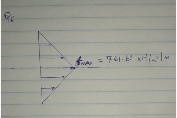
Question 5
Axial stress is calculated by the formula;
We consider only the weight of the blade. Thus,
Calculating A,
Hence, axial stress will be;
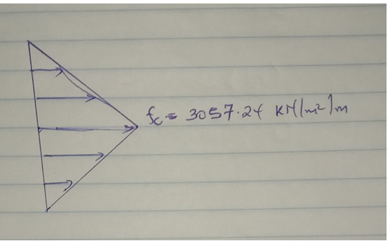
Question 6
Axial stress at the blade root due to the centrifugal force will be obtained as follows (O. A. Bauchau, 2009);
We can now calculate the axial stress as follows;
Question 7
Ratio between the maximum flexural stress and the maximum axial stress due to centrifugal force will be calculated as;
Question 8
Ratio between the maximum flexural stress and the maximum axial stress due to the weight of the blade is given by;
Question 9
The resultant force at the hub due to wind distributed loads is equal to the sum of the resultants at the highest and lowest points obtained in 1.
Question 10
Note that the negative sign indicates the direction of the moment.
Question 11
Try an internal diameter of 1.0 m and external diameter of 1.2 m.
The section modulus will be;
It will not fail. CHOOSE.
Question 12
Weight of blades
Weight of hub
Thus,
Thus,
Question 13
Power
Thus,
It will not exceed.
Question 14
The data;
| Cycles | stress |
| 40 | 260 |
| 500 | 200 |
| 1000 | 160 |
We draw a graph
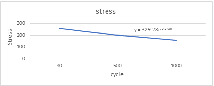
We can now estimate using the equation.
Solving,
Question 15
The shaft. It is in continues motion when the blades are rotating. This builds up to create fatigue in the structure.
The hub. It holds the blades in position and hence the first to overcome the pressure when blades are rotating.
Question 16
References
Jai B. Kim, R. H. K. J. E., 2013. Simplified LRFD Bridge Design. In: s.l.:CRC Press, pp. 54-76.
O. A. Bauchau, J. C., 2009. Structural Analysis: With Applications to Aerospace Structures. In: s.l.:Springer Science & Business Media, pp. 78-124.
Walker, K. M., 2013. Applied Mechanics for Engineering Technology: Pearson New International Edition. In: s.l.:Pearson Education Limited, pp. 112-154.