Q1.a.
b.
Given instruction length is 15 bits, 5 bits are reserved for opcode, 4 bits are reserved for addressing mode. This leaves space for 15 – 5 – 4 = 6 bits for direct and absolute addressing. Giving range of 64 memory locations.
c. In base offset mode, the CPU can access +32 to -31 locations relative to address in base register. By changing base address CPU can access entire memory locations by altering the base address to required range
Q2.
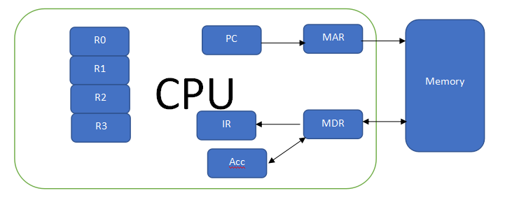
| Step | PC | MAR | MDR | IR | A |
| PC -> MAR | 00101 | X | X | X | X |
| 00101 | 00101 | X | X | X | |
| 00101 | 00101 | 10101011 | 10101011 | X | |
| 00101 | 01011 | 10111000 | 10101011 | X | |
| 00101 | 00101 | 10111000 | 10101011 | 10111000 | |
| 00110 | 00101 | 10111000 | 10101011 | 10111000 | |
| 00110 | 00110 | 10111000 | 10101011 | 10111000 | |
| 00110 | 00110 | 01001100 | 01001100 | 10111000 | |
| 00110 | 01100 | 01110100 | 01001100 | 10111000 | |
| 00110 | 01100 | 01110100 | 01001100 | 00101100 | |
| 00111 | 01100 | 01110100 | 01001100 | 00101100 |
Q3.
| 0x70000000 – 0x7FFFFFFF | Cache – 1MB |
| 0x01C00000 – 0x6FFFFFFF | Empty Space – 483 MB |
| 0x01400000 – 0x01BFFFFF | RAM – 8 MB |
| 0x00400000 – 0x013FFFFF | Module 1 – 16 MB |
| 0x00000000 – 0x003FFFFF | ROM – 4MB |
Q4.
As soon as Laser Printer needs CPU for completing its task. It generates Interrupt request that is forwarded to the INT pin on CPU.
CPU on receiving the interrupt request, completes the current instruction and initiates saving of CPU registers like Accumulator, PC and other status/data registers in to memory location specially reserved for the purpose. This memory area is called the Process Control Block or PCB. Each running process has it’s own PCB area.
Once all current register values are saved in a PCB, CPU switches to execute the Interrupt Serrvice Routine or ISR. Inside ISR, it starts checking on status of each connected device. This is called polling method. The device that generated interrupt would show its status to CPU as source of interrupt.
When CPU determines the printer as source, it branches to ISR of printer and starts executing the interrupt routine for serving the request. Once CPU is done serving the Laser printer, it returns to the previous job by reloading the registers from the saved PCB area and continues further execution where it was interrupted earlier.
Q5.
- Capacity of each block = 512MB / Number of platters X number of sectors X number of cylinders
= 512 MB / 4 X 20 X 800 = 8KB
Cluster capacity = 4 x 8KB = 32 KB
- Transfer Rate = RPM x Number of Sectors x Capacity each sector / min
= 5400 x 20 x 8 KB / min
= 108000 * 8 KB KB / 60 sec
= 14400 KB / sec
= 14.4 MB /sec
- Average Latency time = Period of rotation / 2
= ( (1 / 5400) x 60 ) / 2 sec
= 1/180 sec = 5.55msec
Average Access Time = seek time + Average Latency
= 36msec + 5.55msec
= 41.55msec