Part 1
Fundamental concepts
When the motion of air around the objects are properly understood what is commonly refered to as flow field, then the calculations of the forces as well as acting moments will be possible. Such kind of the modeling is best analyzed at low speed aerodynamics before advancement is made. In the case of low aerodynamic speed, fundamental forces which are of interest include thrust, drag, lift and weight.
Balance of forces during climb
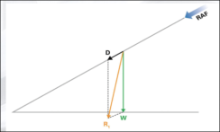
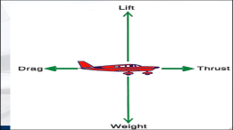
Figure 1: The type of the forces acting on the plane to be balanced (weight, lift, drag and weight (Gubanov 2019).
)
During the process of climbing, the lift of the aircraft must ensure that there is proper weight balance and also the thrust must be higher than the drag or in other words, its value must exceed the drag values. During the process of climb, the plane will use its wings for the purposes of lifting while the engine is meant for the purposes of the thrust. The reduction of the drag is through the smooth design of the plane itself. The management of the weight of the aircraft is managed effectively through proper selection of the materials in the process of the construction.
Figure 2: Conceptual illustration of force balancing
From the above illustrations, the aero plane is actually in the position of equilibrium, there has to be a force which is opposite and equal to the resultant –R1.
Forces Acting Vertically on an Aircraft
Weight
- Earth’s gravitational pull
- Total weight of the aircraft affecting its performance
- Gravitational center offers a single vector which is the point of balance, restricted within the limits, shifts on change of load distribution, influenced by loading effect and point if action of action of the load.
Wing loading
- Weight per unit wing area
Greater loading on the wing increases the distances of take-offs and landing, lowers maneuverability and increases the speed of the aircraft
Lower loading of the wing is the case in which the area of the wing is relatively larger compared to its mass. This lowers the speed of flight while reducing both the distances of take-off and landing as well as stall speed.
Loading on the wing is given by:
Wing loading = (aircraft total weight/ area of the wing)
= 1220/20
= 61kgm-3
Forces acting horizontally within the flight
Thrust
- Propelling force on the aircraft
The backward reaction with the large mass of air results into acceleration of the aircraft and varies with time.
Drag
- Aircraft motion resistance
Balanced forces in flight
Summary of the acting forces on an aircraft
Weight: acts vertically downwards past the gravitational center
Lift: this is the force acting upwards through the axial line of pressure and slightly behind gravitational center and is generated by the wings of the aircraft.
Thrust: generated by the propelling action of the engine
Drag: this is the force that resists movement of any object within the space.
The ration of lift to drag for aeroplanes under flight is considered to be 10:1
Lift production
The resulting lift force on the wings or aerofoil is generated by the relative motion between the aerofoil and the air and is based on the shape of the aerofoil. Due to this, the speed of air either rises or goes down as it flows past the aerofoil.
Part 2
Characteristics and operations of normally aspirated aircraft piston engines
Aircrafts which uses naturally aspirated engines usually have very unique characteristics. The air which is used for the purposes of the combustions (specific types of Otto cycle in the case of the engines of petrol or Diesel cycle in a Diesel engine like for the case of the petrol direct injection or traditional petrol engines with traditional Otto Cycle which uses fuel mixture/an air mixture, is drawn into the cylinders of the engine through the impacts or under the influence of the atmospheric pressure which primarily acts against the partial vacuum. The occurrence of the vacuum takes place during the period when the piston travels downwards as it approaches the bottom dead centre during the stroke of intake.
In summary, it implies that the four stroke engine as illustrated by the Otto Cycle involves a least four processes. The power to turn or drive the crankshaft is provided by only one of the strokes.
At the start of the intake stroke, the volume of the gas is low while the pressure is closed to the atmospheric pressure. There is pulling down of the cylinder as the valve of the intake remains open. There is increase in the volume as fuel is drawn in while the pressure remains constant. When fuel begins undergoing combustion, pressure and temperature increase in the engine. In the power stroke, there is driving of the piston towards the cranks, the pressur5e falls as the volume is increased. This leads into the stage of exhaust in which the volume remains constant as the residual heat is released into the surrounding. There is adjustment of the pressure back to the conditions of the atmosphere. Finally in the exhaust stroke, there is back movement of the piston into the cylinder, pressure remains constant while the volume decreases and the new process commences again.
Figure 3: The Otto Cycle for the 4 stroke engine (Rizzo et al.2018)
Considering that at the inlet tract of the engine, there is innate restriction which usually encompasses the intake manifold, there will be occurrence of the small pressure drop as air is drawn in. This results into the volumetric efficiency which is basically less than 100 percent. Also the value is much lower than the cylinder’s complete air charge (Kaul & Kayacetin 2017).. The air charge density which translates into the engine’s theoretical power output besides being influenced by the restriction system of induction is also influenced by the atmospheric pressure as well as speed of the engine with the former factor decrease sing as the altitude of the operation increases.
Causes of the pre-ignition
“Pre-ignition” in the case of the normally aspirated engines is basically a combustion event considered to be abnormal. It refers to the ignition of the charge of air-fuel during the period when the charge is still being compressed by the piston (Ramiandrisoa & Rakotomanana, 2016). The primary sources of the pre-ignition are caused by the carbon or deposits of lead, cracked spark plug tip in the chamber of the ignition In short, anything this can potentially cause premature ignition of the charge in the chamber of the ignition which definitely results into the pre-ignition in the case of the normally aspirated aircraft engines.
Hydraulic systems
It is usually characterized by the force transmission by the use of pressure generated within the fluids. The aircrafts uses the concepts or the principles of the hydraulics for most of the systems including control of the undercarriages as well as surfaces. The best example for the application of the hydraulic system is the brake components of the aircraft.
Figure 4: Break system of light aircraft using hydraulic principles (Mojaveri, Khorasani & Ahmadvand 2019)
The system has got a reservoir which actually provides the required amount of fluid simultaneously to the required activities. The design of the reservoir is done in such a way that it is pressurized by the atmosphere hence controlling the pump’s cavitation
Figure 5: Hydraulic reservoirs (Uner & Thimsen 2017)
The system of the hydraulic is made up of the power pump which serves to create pressure on the fluid. Its operation can either be done electrically or manually. At the specific joints are filters which are meant trap any debris which might be present in the fluid. During te transmission of the focuses, there is likelihood of pressure building to the excessive level. The pressure regulator valves will be forced open so that part of the fluid of the fluid I sent to the reservoir. The pressure variation is regulated by the use of accumulated gas which acts as spring. The installed check valves at the designated points serves to control the chances of the leakage as well as reverse flow. Some of the valves like selector valves are very useful in changing the path of the fluid flow. In order to order that they remain as effective as possible, they are operated electrically.
Fuel system
The aircraft engine has specific requirement or characteristics of the fuel to be used including being capable of vaporizing easily, having very high content of energy, free from compounds which form gums, sufficient rating of the octane and not having elements of corrosion. This implies that the grading of fuel must be done to ensure that it meets all the required properties including confirmation of the correct color prior to the flight. Gravity feed of fuel is possible in the case of the high wing aircrafts (Boudry, Connolly, & Steiner 2018). However, in the case if the low wing aircrafts there is usually fitted with an engine driven fuel pump which assist in feeding the fuel into the carburetor. In cases considered as being extreme or critical, the supply of the fuel to the pump of the engine will call for use of the electric pumps.
Electrical components of the hydraulic systems
The electrical systems are made up of the battery as well as connection wires primarily. The battery serves as an emergency source of electrical power when the generator fails. Also it serves as a driver to the electric starter of the motor so as to allow for the start of the engine. The operationability of the battery is measured in terms of the ampere-hours. The most preferred battery for the aircraft is the lead-acid battery. They are known for their ability of charging as well as discharging at very faster rates. Also their operations are still efficient even when the temperatures are too high. Most of the aircraft particular the large aircrafts, there are use of busbars. They serve as the most effective points for wire termination in a safe manner. The centre zero ammeters usually assist in the measurement of the flow of current out and in the battery.
Figure 6: Electrical components of the aircraft (Binz, Hartmann, & Moormann, 2018))
Carburetor systems
The primary aim of the carburation is to assist in the conversion of the liquid fuel into the form considered useful for the chamber of the combustion. The fuel of aviation will not undergo combustion unless it is mixed with air. Carburetor works on the principle of the Bernoulli’s i.e. any increase in the velocity results into decrease in the pressure. Getting the right mix of fuel and air is achieved through the fuel injection systems which mixes fuel with air before entry into the cylinder. Also this can be achieved through carburetor which actually mixes air as well as fuel prior to its intake by the manifold. There is vaporization of fuel as it leaves the fuel jets. It then flows into the airstream where it is mixed .with the flowing air. The mixture of air and fuel passes through the manifold inlet where it is mixed properly.
In the case of the throttle butterfly, there is proportional drop in the values of pressure to the flow of air through the throat. The throttle valve is used in the control of air flow rate and it is usually connected to the cockpit level. The throttle is also responsible for the control of air being mixed with fuel.
Idle cut-off system
It helps in stopping of the engine through ensuring that the supply of the fuel is topped at the point of carburetor. It assists in the provision of fuel to the engine system at the point of closure of the butterfly. During idling i.e. when the speed of the engine is low, there is no sufficient airflow which can produce the required pressure drop at the primary discharge nozzle. However, when the butterfly valve is closed, this pressure is likely to be. The small discharge holes on the body of the intake wall thus assist in the spray of fuel into the flow.
Accelerating system
It serves to supply extra fuel to the charge when the throttle is open. Opening of the throttle allows for the instantaneous airflow increase prior to the increase in the fuel flow. The power of the engine thus fades momentarily. This effect is more pronounced with the opening of the throttle. There is connection of the small plunger within the chamber of the throttle which controls this effect through squirt extra fuel into the airflow.
Mixture Control
The best parameter in measuring the correct fuel to air ration is by using the weight aspect. The volume of fuel is metered by carburetor into the air volume. The density of the fuel remains constant whiles the air density changes. Th correct metering of fuel on the basis of weight and volume only takes place at the ome standard density altitude. The weight of the air is expected to decrease where the air density is less but the fuel weight which is being metered remains fairly constant. This makes the mixture richer and the pilot is therefore provided with a means of mixture ratio control. The lever which is red- colored serves to restrict the fuel supply to the carburetor when control lever of the mixture is pulled back besides pulling back the control system to bring the engine into stop.
Oil Systems
The lubricant is primarily used in the reduction of the friction between the moving parts. In fact it serves to prevent contact of metal to metal. There is universal use of the oils in the aircrafts since they can be easily circulated. Oil also helps into forming a seal between the cylinder wall and the piston hence gases leakage are prevented. Oil picks up particles considered as being foreign hence reducing the abrasive wear (Jenkins 2017)..
Impulse coupling
Production of hot sparks is very necessary in the aircraft engines. In order to achieve this, there is use of an impulse coupling magneto. A heavy duty coiled spring is used by the impulse coupling magneto and it is usually tensioned at the process f of the start. Upon achieving the sufficient tension, the end of the spring which is attached to the magnet will be released to spin very fast. This spring of tension is coupled to the flyweights in such a way that immediately the engine starts, there will be disconnection of the mechanism from that of the magneto.
Part 3
Static Pressure and Dynamic Pressure
Static pressure refers to the pressure which the body experiences when the fluid is not in motion or the movement is simultaneous with the fluid. In such cases, the air will be equally pressing on the body from all the directions. Dynamic pressure on the other hand is generated by the body as a result of its motion in the air. The total pressure which the aircraft is subjected to is therefore expressed as : Total pressure = dynamic pressure + static pressure. The measurement is attained by the use of the pitot tube.
Gyroscopes are regarded to be the most essential tools for controlling the common flight parameters such as heading indicator, turn-and-bank turn needle indicator and attitude indicator. The knowledge regarding instrument power systems as well as principles of gyroscopic are necessary to develop a proper understanding on the operation of such instruments. The major component of mechanical gyroscope commonly referred to as the gyro is a rotor or the wheel in which the mass is mainly within the perimeter. The bearing system of the rotor is to enable high speed spinning of the wheel (Auzairy et al 2017).
There is a variety configuration of mounting for the axle and rotor to enable rotational movement of the rotor assembly in either one or two axes in a perpendicular direction to the spin axis. In order to enable free motion of the rotor, it is suspended by the axle which is first fixed on a supporting ring. In case fixing of the brackets is done at an angle of 900 around the ring of support from the actual point of spin axle fixation, the rotational movement of both the rotor and supporting ring is freely at an angle of 3600. For this configuration case, the mechanical gyroscope can be referred to as captive gyro. The rotation can be only on a single axis perpendicular to the spinning axis (Jenkins 2017).
The power for driving the gyroscopes is taken from the air with higher velocity, driven by the use of the electric motors. They are best use as directions indicators, altitude indicators and finally turn coordinator.. This is due to the fact that they tend to be must rigid when in space hence responsible for the creation of the stable platform.
Elementary components of flight and their operations
Classification of the instrument
The elementary instruments of flight can be grouped further into:
- Pitot-static systems: this involve implementing pressure difference (the affected and unaffected ambient air pressure also referred to as pitot and static pressure) in determining parameters of flight comprising of the attitude and the speed of flight of the aircraft.
- Gyroscopic Instruments: this involve use of principles of gyroscope to present information regarding the flight attitude of the aircraft (how the aircraft is oriented with respect to its surrounding).
The Altimeter
This is the model that outlines current height of the aircraft above the sea level rather than the ground surface. The measurements given by the hands of ancient altimeter are in the order of hundreds, thousands and ten thousands of feet. The speeds at which these hand moves are quite different and totally summing together to provide indication of the current attitude of the aircraft.
Airspeed Indicator (ASI)
Airspeed Indicator (ASI) is under the classification of Pitot Static System and is responsible for measuring the aircraft speed during the flight by use of pressure difference within the Pitot tube and the static port. The traditional Airspeed Indicator presents modified values within the round dial hand in the form of a clock that reflects the current speed of the aircraft. The measurement for the speed is usually given in Nautical Miles per Hour shortened as knots and in other instances given as kilometers per hour (Auzairy et al 2017)..
Operation of an Airspeed Indicator
By use of both the aircraft’s pitot and static systems, the airspeed indicator checks on the flow of air and balancing the difference in pressure contributed to by static port and pitot tube externally located to indicate the speed of the aircraft as it moves past the air.
The reading indicated by the model at the ground level of the aircraft is zero due to the equal pressure; infiltration of airborne within the external Pitot tube adds pressure onto the internal diaphragm resulting in upward movement of the Airspeed Indicator.
REFERENCES
Auzairy, N. A., Fun, C. S. F. S., Ching, T. L., Li, S. B., & Fung, C. S. F. S. (2017). Dynamic relationships of capital flight and macroeconomic fundamentals in Malaysia. Geografia-Malaysian Journal of Society and Space, 12(2).
Binz, F., Hartmann, P., & Moormann, D. (2018). Nonlinear Model Predictive Flight Path Control for an Unmanned Powered Paraglider. In Advances in Aerospace Guidance, Navigation and Control (pp. 369-387). Springer, Cham.
Boudry, W., Connolly, R. A., & Steiner, E. (2018). What Really Happens During Flight to Safety: Evidence from Real Estate Markets. Available at SSRN 3178922.
Davies, G., Knehr, K. W., Van Tassell, B., Hodson, T., Biswas, S., Hsieh, A. G., & Steingart, D. A. (2017). State of charge and state of health estimation using electrochemical acoustic time of flight analysis. Journal of The Electrochemical Society, 164(12), A2746-A2755.
Emery, C. M., David, C. H., Andreadis, K. M., Turmon, M. J., Reager, J. T., Hobbs, J. M., … & Rodell, M. (2020). Underlying Fundamentals of Kalman Filtering for River Network Modeling. Journal of Hydrometeorology, 21(3), 453-474.
Gubanov, A. A. (2019). Theoretical fundamentals of airframe/propulsion integration for high-speed aircraft. Advances in Aerodynamics, 1(1), 11.
Jenkins, P. (2017). Space PV Systems and Flight Demonstrations. Photovoltaic Solar Energy, 444.
Kaul, A., & Kayacetin, N. V. (2017). Flight-to-quality, economic fundamentals, and stock returns. Journal of Banking & Finance, 80, 162-175.
Mojaveri, H. S., Khorasani, A., & Ahmadvand, K. (2019). Presenting modified Servqual model to evaluate flight attendant services: Iran Air case study. Journal of Airline and Airport Management, 9(1), 14-23.
Ramiandrisoa, O. T., & Rakotomanana, E. J. M. (2016). Why is there capital flight from developing countries? The case of Madagascar. African Development Review, 28(S1), 22-38.
Rizzo, A., Narici, L., Messi, R., Cipollone, P., De Donato, C., Di Fino, L., … & Morone, M. C. (2018). A compact Time-Of-Flight detector for space applications: The LIDAL system. Nuclear Instruments and Methods in Physics Research Section A: Accelerators, Spectrometers, Detectors and Associated Equipment, 898, 98-104.
Uner, N. B., & Thimsen, E. (2017). In-flight size focusing of aerosols by a low temperature plasma. The Journal of Physical Chemistry C, 121(23), 12936-12944.