Lmi System Overview
Hydraulic cranes are the kind of cranes that use the Load Moment Indicator. This Load Moment Indicator is used in the cranes to read the load’s value of measurement using transducers. In their operation, the transducers make use of pressure. Additionally, in cranes, they take readings on the pressure of the lift’s cylinder. In cranes, the Load Moment Indicator helps to understand the load lifting (Albinger, et al., 2017). With this same mechanism, the load operator is able to understand the amount of load is lifted and if that load being lifted has exceeded. When the crane is in operation therefore, the LMI measures the moment as well as the bearing force in the crane’s arms.
During lifting, if the load being lifted gets beyond the limit that has been set, the crane will automatically develop failures in various stages including structural as well as mechanical failures. The crane operator is supposed to check closely the indication and functionality of the LMI. This is because in the event that the load limit is about to exceed the set limit or has gone beyond this limit, the system will give a signal to the operator (Bohnacker, et al., 2015). This in return prevents the falling of the crane’s arm.
As part of calculation, there is inclusion of boom weight in the general crane load determination. Effects like wind and ice usually affects the load’s general weight. The LMI system is meant therefore to calculate the effects of these elements.
Lmi Systems In Cranes
The LMI system comprises of the Length transmitter as well as the Angle systems in cranes. Other systems that are part of the LMI are the load plate system, Anti-two block, Angle and the wind speed sensor systems.
Angle sensor system
The system is among the significant LMI systems. Through it, the position as well as the steering wheel angle being used by an operator can be measured. The angle that the steering wheel turns can also be rated by this system (Schneider, et al., 2011). This sensor has been fitted with tool for scanning which helps to provide data on the degrees the wheel has been able to turn as well as its position in general. In the steering column, there is a sensor cluster where this sensor is located. A crane will always have two systems of this kind. This is for purposes of confirmation of data as well as avoidance of redundancy of the data.
The two systems do not depend on each other at all. Further, each of them gives different data. By analyzing the data from the two sensors, an operator is able to be sure about the operation.
Angle and Length Transmitter system
This system is part of LMI system of a crane. It is meant to take the measure of the cylinder and the telescoping cylinder’s angle in comparison with the force of gravity. Every crane utilizes this system because with it, the system can measure both the boom angle and the boom length (Fang, et al., 2013). This system however cannot resist some surroundings and particularly in conditions that are harsh. The sensor system may be removed for mobile cranes. In measuring the general length, this system contains a cable reel that is estimated to be 32 feet. Also, it has a 30mm resolution length, 0.2 degree accuracy angle, 0.2 degrees resolution angle and accuracy length of about 30mm.
Wind speed sensor system
Any crane has been designed in a unique way that in places of unconducive environments like places with very high wind speeds, it cannot function. This is deliberately done to ensure the crane and its operator’s safety. This sensor system is then incorporated in cranes to measure and determine that place’s safety before the operation as well as during the operation itself. During times of high rates of wind, the sensor in the crane will signal the operator to take the required measures. This wind speed sensor has a set limit. The sensor will determine if the limit has been exceeded (Huang, et al., 2013). It will send the relevant signal to the operator on the dashboard. The operator will then evaluate if it is safe to continue with the operation. If it is not, the operation will have to be stopped.
Load plate system
The load plate is a space for loading where a load is at first placed before being transferred to another vessel. This system is employed in cranes that are meant to load and offload loads that are extremely heavy for example steel materials like plates, coils, tracks and ocean vessels (Willim, Hans and Yggve, 2015).
The load plate should be able to develop a force that is so strong that it can handle an extra palate meant to load wide loads or ships.
The system should also be able to manage wide leg used to offload and even load in each cycle with no slewing.
Anti-two Block sensor system, A2B
This system is mainly employed to convey warnings to two block condition operator in a crane (Ethington, B.G and Oshkosh, 2014). The lower hook of the crane being lifted until it touches the crane boom hardware is what is called two-blocking condition. Sometimes, the lower and upper parts of the pulley touches each other. The contact of the two parts is the origin of the term A2B. The condition of two-blocking may occur when telescoping the boom out and when booming down the crane. Whenever any of these happens, the crane’s lower hook will eventually draw above the upper side of the sheave (Williams and Saker, 2019). This sensor system will then prevent the crane’s hook block from crashing directly with the boom head. This is likely to happen during load lifting. The counter weight is applied to ensure the contact switch remains closed. This system will prevent the hook block from hitting the boom weight and instead hit the counterweight. As a result, the counter weight will open the contact by rising and as such, the switch needs to be of high reliability and be able to withstand all weather and climate conditions.
a Typical Lmi Design
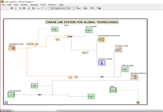
a Measurement System Block Diagram
EXPERIMENTAL CRITICAL ANALYSIS
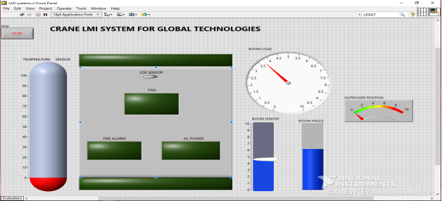
There is a requirement by the research that these sensor systems should be analyzed by NI LabVIEW and DAQ software. This is done below.
The Anti-Two Block Sensor System
As already mentioned, this system prevents and warns the operator of a two block condition in cranes. This critical condition rises from a situation where crane lower hook is lifted so high until it touches the crane boom hardware (Kalairassan, Boopathi, and Mohan, 2017)
Using NI DAQ for the analysis, the results are that the boom weight as well as the hook block are both monitored at about 15 inches. This is according to this analysis. This is a complete opposite of the case when NI LabVIEW is applied. In this case, only 5 inches separates the hook block from the boom weight, a distance that is so close and therefore dangerous in an event of a mechanical malfunction or a simple mistake or system failure. If any of these happens, a crush on the system’s upper side between the boom weight and the hook block will be experienced. This possibility is proven by the fact that wind may sway off the load being lifted hence closing that gap and eventually bringing the effect (Singh, et al., 2011)
Wind Speed Sensor system
In a normal situation, the design of any crane is that it cannot work in high wind speed places (Hasan, et al., 2012). This guarantees the operator’s as well as the crane’s safety. This sensor is therefore incorporated in the cranes to measure and evaluate the safety levels before operations and during the operation as well. At any point when the speed of wind is quite high, the operator will be in a position to get signals from the sensor for the required action to be taken. These signals will be portrayed on the dashboard.
If NI DAQ software is used to analyze this critically, the sensor is able to take measurement on the wind speed according to its intensity. This can be obtained from the load. Whenever the wind speed is above 45km/h, this high speed will be detected by the sensor which will then suggest that the crane operations be stopped immediately. With this software analysis therefore, the wind speed limit that has been set is constant and cannot change even if there is changes in temperature, which is likely to influence the wind’s intensity. When employing the NI LabVIEW software during analysis, the wind speed is seen to be influenced by temperature as well as the humidity present in the atmosphere (Zhou, et al., 2012). This results in a situation where the limit of the wind speed could vary and range from 43km/h to 48km/hr. Using NI DAQ software in the wind speed sensor analysis therefore proves to be sustainable and also has high levels of accuracy for the operations of cranes.
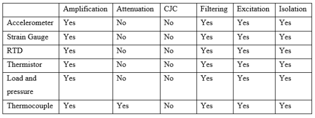
SIGNAL CONDITIONING ELEMENTS EVALUATION
In the evaluation of LMI system, signal conditioning is quite crucial. This is because it provides information on the system of measurement being employed in the LMI system of a crane (Chi, et al., 2012). As seen in the following table, it is very crucial to study and understand the conditioning of signals for all kinds of measurements.
NEXT PHASE OF DEVELOPMENT
- Creating and expanding low cost systems as well as controllers.
Creation and expansion of the current LMI systems is very high in terms of cost, making a crane’s total cost to be extremely high. Working towards design and development of modern sensors as well as systems is significant (Koivumäki and Mattila, 2015). This is because it will lower the general costs and make the systems affordable.
- Instead of using the current mechanized ways of data transmission, usage of both wired and wireless ways.
The current crane systems employ mechanized ways of data transmission to the dashboard for the viewing by the operator. This is a slow way of transmitting information compared to modern technologies (Fang, et al., 2016). The Introduction of the usage of wireless as well as wired modes of transmission should be done to lower the general system cost and also ensure faster conveyance of information to the intended users during design and operation of cranes.
- Utilizing the Internet of Things, IoT.
IoT is the most present day technology that is driving the whole world to new phases of technology. With this technology, if introduced in the cranes, the dashboard could be kept in the cloud. Later, this information can remotely be accessed at any time and from anywhere (Hyla, 2012).
CONCLUSION
As already identified, for accurate and reliable results, the application of the NI DAQ software is recommended rather than use of NI LabVIEW software for analysis. It is therefore advisable to introduce the use of NI DAQ software in designing and developing LMI systems of cranes. Further, to make the system more modern and cheaper, the latest technology should be employed.
REFERENCES
Albinger, T.J., Taylor, J.W. and Nysse, B.N., Manitowoc Crane Companies Inc, 2017. System and method for crane counterweight positioning. U.S. Patent 9,783,395.
Bohnacker, R., Kenzelmann, M. and Spaeth, H., Liebherr Werk Ehingen GmbH, 2015. Method of monitoring crane safety during the setup procedure, as well as crane and crane control. U.S. Patent 9,120,653.
Chi, H.L., Chen, Y.C., Kang, S.C. and Hsieh, S.H., 2012. Development of user interface for tele-operated cranes. Advanced Engineering Informatics, 26(3), pp.641-652.
Ethington, B.G., Oshkosh Corp, 2014. Anti-two block system for a crane assembly. U.S. Patent 8,813,981.
Fang, Y., Cho, Y.K. and Chen, J., 2016. A framework for real-time pro-active safety assistance for mobile crane lifting operations. Automation in Construction, 72, pp.367-379.
Fang, Y., Wang, P., Sun, N. and Zhang, Y., 2013. Dynamics analysis and nonlinear control of an offshore boom crane. IEEE Transactions on Industrial Electronics, 61(1), pp.414-427.
Hasan, S., Zaman, H., Han, S., Al-Hussein, M. and Su, Y., 2012. Integrated building information model to identify possible crane instability caused by strong winds. In Construction Research Congress 2012: Construction Challenges in a Flat World (pp. 1281-1290).
Huang, J., Maleki, E. and Singhose, W., 2013. Dynamics and swing control of mobile boom cranes subject to wind disturbances. IET Control Theory & Applications, 7(9), pp.1187-1195.
Hyla, P., 2012, August. The crane control systems: A survey. In 2012 17th International Conference on Methods & Models in Automation & Robotics (MMAR) (pp. 505-509). IEEE.
Kalairassan, G., Boopathi, M. and Mohan, R.M., 2017, November. Analysis of load monitoring system in hydraulic mobile cranes. In IOP Conference Series: Materials Science and Engineering (Vol. 263, No. 6, p. 062045). IOP Publishing.
Koivumäki, J. and Mattila, J., 2015. High performance nonlinear motion/force controller design for redundant hydraulic construction crane automation. Automation in Construction, 51, pp.59-77.
Schneider, K., Sawodny, O. and Neupert, J., Liebherr Werk Nenzing GmbH, 2011. Crane control, crane and method. U.S. Patent 8,025,167.
Singh, B., Nagar, B., Kadam, B.S. and Kumar, A., 2011. Modeling and finite element analysis of crane boom. International Journal of Advanced Engineering Research and Studies, 1(1), pp.51-55.
Williams, T. and Saker, T., Keppel Letourneau Usa Inc, 2019. Anti-two-block sensing systems. U.S. Patent 10,233,058.
Willim, Hans-Dieter, and Yggve Richter. “Load hook control device for a crane.” U.S. Patent 8,944,262, issued February 3, 2015.
Zhou, L., Tian, Y., Roy, S.B., Thorncroft, C., Bosart, L.F. and Hu, Y., 2012. Impacts of wind farms on land surface temperature. Nature Climate Change, 2(7), p.539.