SECTION A
Q1,
POTS is an acronym for plain old telephone service. Its Main components are Switch and trunk.
ASDL stands for Asymmetric subscriber line. Main components are CPE and DSLAM core.
b)
i) A is traffic expressed in erlang l/m
ii) N is the number of channels available
iii) The percentage numbers from 0.7% to 40% represent the percentage of time spent in the respective state which translates to the percent of calls being blocked
C) Done in the photo
d) The 350 channels – imply cluster of 21 hence 350/21 = 16 per cluster thus the number that would give 2% call blocking is 10 channels per cell
Q2
a)
i)
Assuming omnidirectional, lossless and receiver antenna is in the far field of transmitter antenna/. Then the power transmitted can be related to the power received as follows:
Power density on the plane wave at distance R from transmitter is:
If the transmitter antenna has a power gain of
The power density of the transmitted wave is
If the receiver has an area which can be expressed as
The power becomes
But can be expressed as the effective area given by:
Then power received by the antenna is:
ii) The physically important parameters of the above equation are:
R – radius – distance of the receiver from the transmitter antenna.
b)
i) Provided
ii) The gain at 3.072Km is given by
Q3)
a)
i) Cell radius
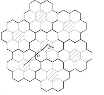
This is the distance from the point of antenna location to the area where signal no longer operates
This is the distance within which as cell with similar frequency can be placed.
iii) Cluster and cluster size
cluster is a group of cells operating under one major cell unit
cluster size is the number of cells in the cluster
b) Quantization as used in pulse code modulation, involves dividing the signal into segmental levels, any pint that falls in a given segment is are approximated with corresponding quantization level
Quantization noise is the inherent error that occurs during the quantization of the analog signal into digital and Vis a Vis.
c) effective height of antenna is 2-0.8 = 1.2m
D = = 120km
Q11
i) It is assumed that the shadow fading, power control features and multi-channel reuse groups are ignored.
ii) Cell sectoring is the replacement of an Omni directional antenna at the base using several direction antennas. This helps to reduce co channel interference
iii) Carrier to interference ratio changes as follows:
Where K factor is due to increased antenna
iv) D = 5.R
Q20,
a) time division multiplexing is a technique of sending and receiving signals that are independent by use of synchronized switching such that only an independent signal appears on line for fraction of time for T1 system, sampling rate = 125usec, for 24 channels *8 +1 = 193 bits per frame.
Hence the TDM PCM technique has 193/125 = 1.544 Mbit/sec
b) Pulse code modulation steps:
1. Sampling
Sampling is the measuring of analog signal at specific intervals. Nyquist rate is applied during sampling
2. Quantization
This is the allocation of a digital number to the measures signal to determine the strength.
3. Coding
This refers to the adding and conversion of the bits to conform to the required format for transmission.
c) Plane earth propagation loss
Where h1 is transmitter height, h2 is the receiver antennas height and d is the distance of separation along the ground.
Thus the loss of plane waves is affected by geographical location of antennas and their heights location.
Q21,
a)
i) The sampling frequency this is because each bit occupies 125uSec
ii) Frame rate is given as: 1000Hz since for the PCM sample rate and frame rate need be equal
ii)
b)
i) The n percent of subscribers/load, T – traffic erlang number, W calls in a cell
ii) Mean duration of call
SECTION B
Q4
a)
b) Link bandwidth required to convey the information is
c) Carson’s rule
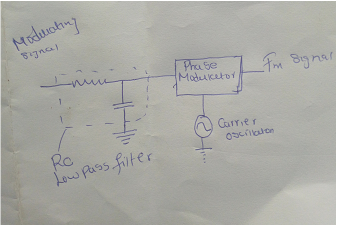
d) Sketch of fm using phase modulator
Q5
a) Isotropic point source is an EM wave radiator that radiates waves of same intensity in all direction
Power density of a wave is the intensity of power of a wave per unit area.
b) Attenuation is the diminishing in the strength of a wave as it progresses in time and space. It may never get to the receiver if it is attenuated greatly. The receiver may also receive a weaker signal compared to transmitted signal Proakis & Manolakis, (2018).
Reflection is the bouncing of wave to a different direction when it it’s a surface. For a line of sight transmission, the waves may go away from the receiver to different direction.
Diffraction is when part of wave is refracted to a different direction and only part gets to receiver.
Scattering is when a wave is reflected randomly to different directions hence only small signal or part of it is received. The transceiver may be affected
Q6
Power received at the mobile phone is given as
Rms voltage at receiver input
Q7
- Noise factor of an electronic amplifier is the measure of degradation of a signal fed into the amplifiers to noise ratio in an amplifier
Signal power = =
Noise power =
SNR = 37.74
Desired output signal is
The noise output signal is 5/37.74 = 0.132Mv
C) Overall noise factor =
F =
F
The bandwidth of receiver
= 2.3 GHz
Q8
Virtual height =240km, electron density N = , distance between points =650km
Critical frequency
Maximum usable frequency:
Where is the angle of incidence and is the frequency of oblique incidence
Calculating , we have where
= 2.163 hence the
Q9
a) Explain the term fading as used in wireless communication
Fading refers to as the variation that occurs on a signal due to various variables.
b) Primary causes of fading
Primary causes of fading include factors such as geographical position, time and frequency.
Models of fading include: Nakagami and Weibull distributions
c) Four modes of electromagnetic wave propagation
1. Transverse electromagnetic mode TEM mode
2. Transverse electric mode – TE mode
3. Transverse magnetic mode – TM mode
4. Hybrid modes
d) Power at the receiver is given as:
The attenuation per kilometer is 0.5
Hence the attenuation added to the signal 10km away is given as: 0.5X10 = 5dB
The power at the receivers end is:
Magnitude of electric field under heavy rain conditions is given as:
Q10
a)
Spectrum of AM signal
b) Single sideband suppressed carrier is preferred over full AM wave since it saves bandwidth for transmission.
Advantages of single sideband suppressed carrier
- It saves energy since the electrical power needed for transmitter is reduced
- The other bandwidth could be used for other purposes.
c) i)modulation index
ii) Carrier power
iii) The total power is
iv) Fraction of carrier power is:
v) The bandwidth required to transmit this signal is: 2fc = 2X45 = 90 KHz
vi) Sideband power= modulation index x carrier power/4=0.4035×770.67/4=77.74w
vii) A typical audio frequency of 3000 Hz will have a wavelength of 100 km and would need an effective antenna length of 25 km.
d) Modulation frequency from oscilloscope
Q11
a)
- Calculate the impedance
- Power density
b) Effects of ionosphere on different bands
Ionosphere absorbs the VLF waveband signal at small percentage leading to some attenuation which leads to propagation losses. However, phase velocity of the group is affected by the D layer of ionosphere which affects the apparent height with 92km being the height for night and 80 km being the height for the day. When a signal has its electric component normal to the sphere, and its incident angle is large then there is no change in polarization during reflection
LF
Low frequency signal is reflected by refraction mechanism which makes them travel for long distances larger than 320km Proakis & Manolakis, (2018).
Q12
b)
i) The concept of cluster size K is whereby a group of all adjacent cells are using total frequency assignment of the system.
ii) Minimum acceptable size of cluster is 4, this is because 4 is the minimum number of cells that can fit like a jig-saw
ii) Hexagonal systems are used for design and analysis of cellular systems since they would not leave a black spot
c)
For 210 channels and cluster size of 4 cells;
There has to be210/7 = 30, assuming call blocking of 3%, the maximum acceptable channel allocation would be 6 channels per cell
D 280 channels with a cluster of 10 would imply 28 channels per cell, for 3% blocking then, the value of A for blocking probability is 14
Q 13
a)
POTS is an acronym for plain old telephone service. Its Main components are Switch and trunk
ASDL stands for Asymmetric subscriber line. Main components are CPE and DSLAM core
b)
i) Aliasing refers to the error that occurs when a signal is reconstructed from the transmitted form
ii) Quantization noise is the inherent error during the encoding of a digital signal
C
i) The significance of the equation physically is:
It relates the height of transmitter and receiver antennae with distance of separation to the losses associated with them.
ii)
The equation:
Hence the distance
Q14
a)
It is done so that a digital signal can be transmitted via a channel that is carrying analog signal.
Amplitude Shift keying technique is where the magnitude of carrier signal is changed according to the signal to be transmitted
Phase Shift keying technique is a form of modulation where a digital signal modulation is achieved by varying the cosine and sine input parameters in order to change the phase of the signal Yaroslavsky, (2017).
Frequency Shift keying technique is where the frequency of carrier signal is changed according to the signal to be transmitted
b)
The ASCII uses 7 bits
This is because the 8 bit is common storage for byte hence other characters from foreign languages and symbols are given a room
c) With reference to analogue modulation techniques
QAM stands for Quadrature amplitude modulation. This is where an in-phase signal and quadrature phase are modulated and then combined/ summed in finite amplitude number.
QAM is applied in
1 digital celluar in Japan
2 Modem voiceband signals
3 Optical fiber systems
Q15
i) A is traffic expressed in erlang l/m
ii) N is the number of channels available
iii) The percentage numbers from 0.7% to 40% reprecent the percentage of time spent in the respective state which translates to the percent of calls being blocked
Q 16,
a) Fresnel zone refers to an ellipsoid that stretches between two antennas.
b)
i) The radius of the first Fresnel zone
Where
ii) The factor for mounting is given as
The minimum mounting height is 55metres
Q17
a) Transmission system may suffer from noise due to:
Thermal noise – components may increase generate further signals or distort the signal due to increased temperature. This can be reduced by using system components with higher tolerance of temperature
Electromagnetic interference- This could be due to external sources of radiation which, may induce some noise
Manufacturing defects – Capacitors and other components may appear in manufacturing of equipment hence may be source of noise during operation Yaroslavsky, (2017).
b) Thermal noise for each of resistors
The noise power
ii)
When the resistors are connected in series,
Total resistance is 25 000 ohms
Hence the
When the resistors are connected in parallel,
Total resistance is 4 000 ohms
Hence the
Iii
a) N=kTB
k- Boltzmann constant= 1.38 x 10⁻²³
B-band width
T- Effective Temperature
= (35 + 52+40) x1x106x1.38 x 10-23
= 1.7526×10⁻¹⁵
b) N=kT
= (35 + 52+40) x1x106x1.38 x 10-23
=1.27×10⁶
Q18
a)
Advantages of FM over AM
The signal to noise ratio is improved
Smaller interference between close areas
Less power is spent
Bandwidth is spent more efficiently
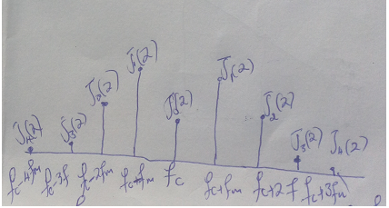
i) Total power in the FM signal is given as
ii) Modulation index is given as
Where
Which is 0.5
iii) Peak frequency deviation =
iv) The modulator sensitivity
V) The power spectral becomes:
vi) Bandwidth
vii) Total information power
= 300*
= (354/50)*354
= 2506.7W
Reference
Proakis, J. G., & Manolakis, D. G. (2018). Digital signal processing. Harlow, Essex, Pearson.
Yaroslavsky, L. (2017) Digital Signal Processing in Experimental Research Volume 1: Fast Transform Methods in Digital Signal Processing. Sharjah, Bentham Science Publishers. Available from: http://public.eblib.com/choice/publicfullrecord.aspx?p=864334. [Accessed Date: 3rd March 2019].