Introduction
This document is a proposal for a feasible network design for an insurance company. The company is based in Melbourne and recently opened a branch in Sydney. The two branches are connected together via the internet through a wide area network. The company server is located at Melbourne which is the headquarter. Users in Sydney are in need to access the information in the server in Melbourne and also transmit and communicate data. The data contains confidential information such as customer names, addresses, and phone numbers.
Project scope
The purpose of this project is to design a wide area network that will serve the two insurance company offices, one at Melbourne and the other at Sydney. Each of the separate offices will be served by a local area network (LAN) [1]. LANs must be created in both of the company locations to facilitate communication and information sharing among the employees. The company has been broken down into several different departments to aid in task or work division. This will force the local area networks in each location to be broken into various virtual area networks (VLAN). Each VLAN will represent a workstation which represents a workstation in this case scenario.
The networks will be divided into subnets to serve all the departments and at the same time merge them to work as one. To facilitate communication between the two locations, a wide area network (WAN) is needed [2]. It will merge the two separate local area networks via the internet. Give that the internet is a public network, the wide-area network needs to be protected via firewalls. Each gateway to a local area network will be connected with a firewall to block any external network from gaining entry into the network. The purpose of having a gateway is to direct the data traffic in and out of the two local area networks under the WAN. The two networks will be connected through a virtual private network (VPN) which allows the creation of a secure network over a less secure network such as the internet [3].
Project requirements
Project hardware requirements are the network physical devices required to implement the proposed network design. Network connectivity is key in achieving the purpose of the network since it defines how the network components are connected to each other. The quantity of the network components will depend on the number of workstations needed in each branch. The following network devices are necessary to create the design.
- Router – A router facilitates network connectivity in a network and is responsible for directing network traffic. Routers in this network will work as gateways to the LANs.
- Switch – Switches will be used to outsource the two LANS before merging them together and will also extend the network to various workstations.
- Cables – Cables will be used to connect the network devices together.
- RJ45s – This will be used to terminate the cables to facilitate the connection between the devices.
- Server – The server which is will be located at Melbourne will be used to store data.
- Firewall – Firewall will be used to secure the virtual private network from malicious external networks.
Ethernet
The Ethernet cables will be used for connecting computers within the branch. Shielded cables will be used outside the buildings the other cables will be used inside the buildings. It will be used in this case since it transfers data from one department to another by the use of protocols. More, it some cheap than other sources of data transfer[4].
VPWS
The virtual private wire service is the control plane for BGP that is used for point to point connection. It has encapsulation techniques for establishing EVPN connection among the switches.it will be implemented in each switch that’s is found in the network. It helps as eliminate single-segment connection among different devices.
VPLS
This is a way to provide Ethernet-based multipoint communication that is done over IP networks. It allows sites that are geographically located far a way to communicate with each other by connecting with each through the Pseudo WIRES. This can be the network from differences.
Network design
The two LANS will connect to the internet via a virtual private network. The LANs will utilize the star topology network design. Star topology networks have a source computer at the center of the network which then spreads out the workstations. These networks are more suitable to use in this kind of company network where a large amount of data is involved. Compared to the other network topologies such as linear topology and ring topology, star topology is much efficient in terms of network latency and throughput. It has high latency is the time required to transmit a packet of data from source to destination [5]. Star topology networks also have high bandwidth which is the actual speed of data transfer.
It is easy and faster to detect a fault in star topology than in ring topology. Merging the two LANs together creates a big wide network and it mare be disadvantageous using a topology that complicates the whole network in case of a fault. A fault is one workstation does not cause a failure of the whole network. In a case on ring networks, a failure of one LAN would affect the whole WAN and this can also create a loophole thus vulnerability to an external attack since the network is connected via the internet [6].
Based on the communication and data transfer between the two branches, the best architecture to use in the network design is a peer-to-peer network architecture. It allows file sharing between members on different networks since all the users are given equal power to communicate. Though it supports resource sharing, client-server architecture only gives the server computer power to communicate to all the other user on the network. This will limit the communication power since a user has to request for resources and services and the server responds according to its task scheduling and resource availability.
Network design topology
Figure 1: Network digram
The above logical design of the network between Sydney and Melbourne. The two branches are connected together through three routers as shown in the above diagram. One router is located at Melbourne another router is located at Sydney. Another router is located between the two and links the network to the internet.
Network addressing
| DEVICE | INTERFACE | IP ADDRESS | SUBNET MASK |
| R 1 | FA 0/0.2 | 10.8.11.1 | 255.255.255.0 |
| SE 0/3/0 | 214.72.189.2 | 255.255.255.0 | |
| SE 0/3/1 | 129.42.105.2 | 255.255.0.0 | |
| R 3 | FA 0/0.2 | 56.172.1.1 | 255.0.0.0 |
| SE 0/1/0 | 146.210.18.51 | 255.255.0.0 | |
| SE 0/1/1.201 | 129.42.105.3 | 255.255.0.0 | |
| ISP | FA 0/0 | 192.168.0.1 | 255.255.255.0 |
| SE 0/0/1 | 146.210.18.49 | 255.255.0.0 | |
| SE 0/0/0 | 214.72.189.3 | 255.255.255.0 |
Table 1
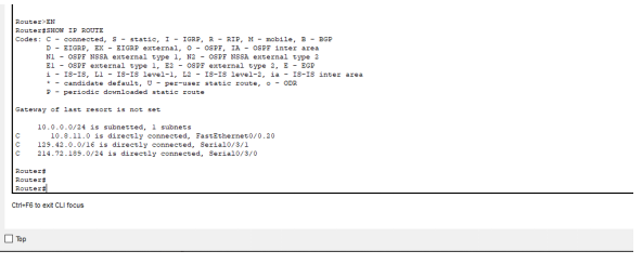
R1
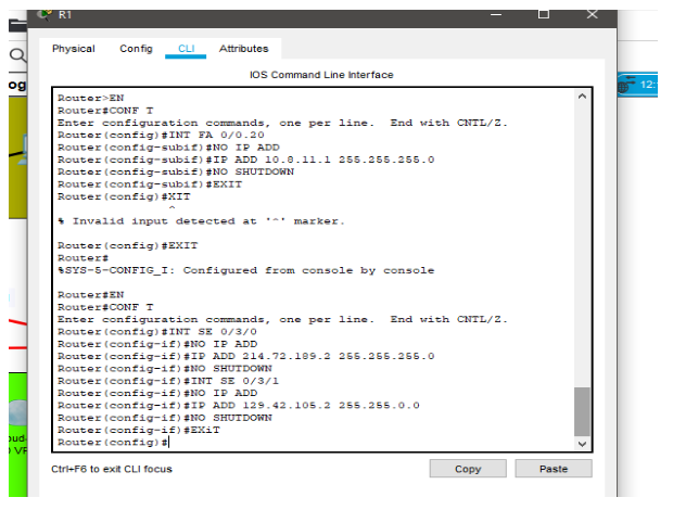
Figure 2: Configuring R1
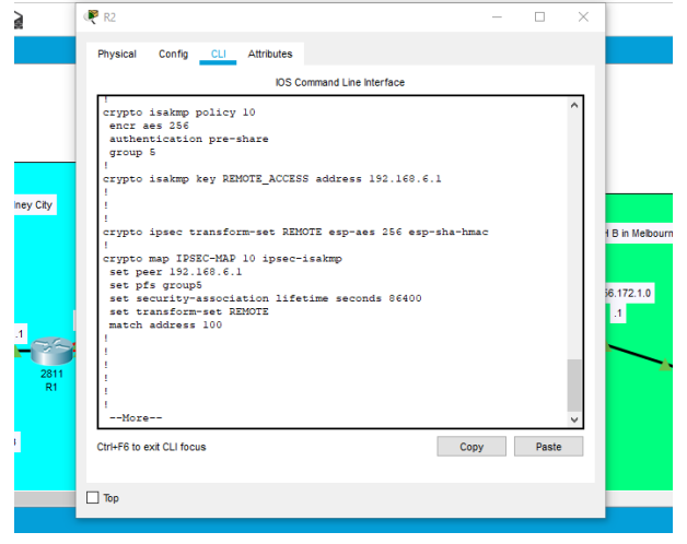
Configuring the routers
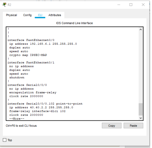
Figure 3: Configuring R2
R3

Figur 4 : Configuring R3
Figure 5 : Configuring R3
ISP
Figure 6 :Configuring isp
Figure 7 Configuring 1SP
Configuration of the Gateway and firewall
The network between the two sites is connected through a VPN connection [7]. This because VPN is a secure technology that’s will promote secure communication between the two sites.
It is configured in both routers as shown below.
Figure8 : VPN configured in the routers.
Figure 9 :IPs and vlan configured in the network.
Figure 10: Trunk mode is enabled in the switches.
Analysis and Evaluation
Figure : Vlan configured in the switches.
Analysis and performance of the network
The implementation of the networks using a VPN between the sites will enhance secure communication between the two sites. Devices between the two sites will be able to ping between each other without a lot of easy. The flow of packets will not interrupt by external factors e.g destroyed transmission cables [8].
Also, the network will be easily monitored by software like Zabbix. Thus any problem in the network will be easily identified and corrected at an early stage.
Conclusion
In end the utilization of VPN system greatly affects the developing endeavors as it enables the venture to intently screen its clients while completing their tasks remotely without being at the primary branch station . it likewise permits the separating of the bundles that are entering the system by blocking parcels from the obscure destinations and it permits the sharing of records between the system. all these permits the better execution in the undertaking and prompts its development. The dependable and accessible for all the web clients and through this the association will have the option to serve their clients from anyplace on the web. It will enable the two sites to communicate with each other without facing any issues.
References
Network design. Burks Falls, ON: ASM Advanced Strategic Management Consultants, 2010.
A. Bianco and F. Neri, Next Generation Optical Network Design and Modelling. New York, NY: Springer, 2013.
A. Gagliardi and S. Alhabib, “Trends in guideline implementation: a scoping systematic review”, Implementation Science, vol. 10, no. 1, 2015. Available: 10.1186/s13012-015-0247-8.
K. Grewal and R. Dangi, “Comparative Analysis of QoS VPN Provisioning Algorithm on Traditional IP based VPN and MPLS VPN using NS-2”, International Journal of Computer Applications, vol. 48, no. 1, pp. 43-46, 2012. Available: 10.5120/7316-9922.
N. Sulaiman, S. Syed Ahmad and S. Ahmad, “Logical Approach: Consistency Rules between Activity Diagram and Class Diagram”, International Journal on Advanced Science, Engineering and Information Technology, vol. 9, no. 2, p. 552, 2019. Available: 10.18517/ijaseit.9.1.7581.
A. Bianco and F. Neri, Next Generation Optical Network Design and Modelling. New York, NY: Springer, 2013.
W. Manning, CompTIA network+. Brisbane, Australia: The Art of Service, 2011.
IT managers fail to receive support for security policies”, Network Security, vol. 1998, no. 4, p. 5, 1998. Available: 10.1016/s1353-4858(98)90099-x.