Each piece is connected to a different server as shown below

The network was completed as shown above. The hierarchical network architecture was used in this case. The network is divided into the different layer as shown above. The core layer has the routers, the distribution layer will have the layer 3 switch while the access layer will have the access switches shown below. The access layer is used to connect the end device of the network with the other core layer of the network. The VTP domain is used in this case such that switches are configured as a client while the switches are configured as servers. The VLANs are then configured in the server switches the client hen inherits all the properties of the VLANs that are configured in the server switch. The following code was used in implementing the VLANs in the network. The pcs from different networks are found in different flows as shown in the above diagram. This means the VLANs configured in the network can be accessed from any section of the levels.
Vlans propagation secured
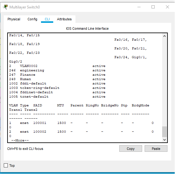
The VLANs were configured in the network as shown below.
The ports between the server and the client switches are then set into trunk mode so that they can allow all the VLANs int the network to flow from the end of the network to another. This make s the network process to be easy since one does not have to configure the VLANs in each switch. The DHCP is also configured in the so that Ip addresses can be allocated to devices automatically. We have a DHCP server then carries out the functions that are mentioned. The following code also can be used in configuring the DHCP in the routers.
The VLANs configured in the network as shown above. The following vtp codes are used in propagating VLANs from layer 3 switch to the layer 2 switches.
vlan database
vtp domain jama
vtp client
vtp password 6696
config t
int range fa0/5-13
switchport mode access
switchport access vlan 12
exit
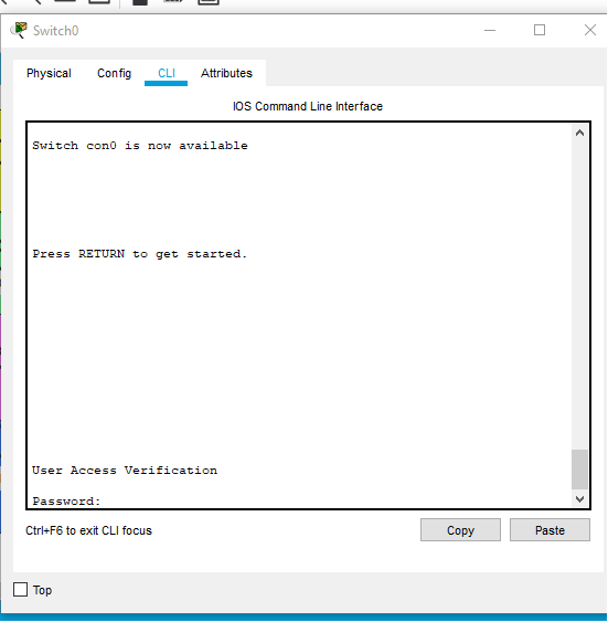
All switched implement login
The logins were configured in the network as shown below using the commands
line console 0
password class
exec-timeout 0 0
login
logging synchronous
line aux 0
password ciscoauxpass
exec-timeout 0 0
login
line vty 0
password cisco
exec-timeout 0 0
login
Passwords configured in the switches as shown below
Unused ports closed
Unused ports closed

DHCP is configured
The followin commands were used to configure the dhcp
Switch(dhcp-config)#default-router 192.168.247.1
Switch(dhcp-config)#exit
Switch(config)#ip dhcp po
Switch(config)#ip dhcp pool pl
Switch(dhcp-config)#network 192.168.248.0 255.255.255.0
Switch(dhcp-config)#de
Switch(dhcp-config)#default-router 192.168.%DHCPD-4-PING_CONFLICT: DHCP address conflict: server pinged 192.168.248.1.
Switch(dhcp-config)#default-router 192.168.248.1
Switch(dhcp-config)#%DHCPD-4-PING_CONFLICT: DHCP address conflict: server pinged 192.168.247.1.
%DHCPD-4-PING_CONFLICT: DHCP address conflict: server pinged 192.168.248.1.
This allocated IP addresses dynamical to the ones that are being configured manually in the devices. This enables devices to communicate with each other without phasing any network issues.
The passwords are configured in I the network in order or prevent an unauthorized user from accessing the network. The following codes were used in this.
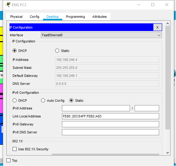
The devices are being allocated Ip addresses dynamical