- Introduction
This report presents the analysis of a 6-DOF manipulator arm for space applications, able to capture satellite debris such as Envisat. It encompasses the entire process of development beginning from kinematic equations to dynamic simulations based on MATLAB for computational modeling. The goal is to develop a practical technique for computing the manipulator’s trajectory, control strategies, and torques required to have accurate location and orientation of the end-effector. This study uses the Denavit-Hartenberg convention for forward kinematics and inverse kinematic solutions to address this urgent requirement of effective debris removal in space, which aims at averting possible threats. Dynamic modeling and the visualization of arm movement highlight its practical implications as well as technological readiness. The completion of this task not only supports the direction towards robotic space operations but also provides recognition to complex environments for advanced simulation in developing mechanisms, with a reassurance; of safer and cleaner orbital space.
- Design and Methodology
These equations play a crucial role in the control of robotic arms and simulations, allowing us to determine the end-effector position and orientation based on given joint angles. The Jacobian is an important factor in determining variations of joint angles will affect the velocity of the manipulator and so it is essential for control strategies such as trajectory planning and inverse kinematics problem-solving. The D-H convention modifies the complicated geometry of manipulators to a standard form so that robotic arms can be modeled and simulated with ease. We proceed as follows;
- Kinematics
The kinematics of the manipulator describe how the position and orientation of the end-effector (the grapple point) are related to the joint angles. For a 6-degree-of-freedom (DOF) manipulator, this typically involves a serial chain of six joints.
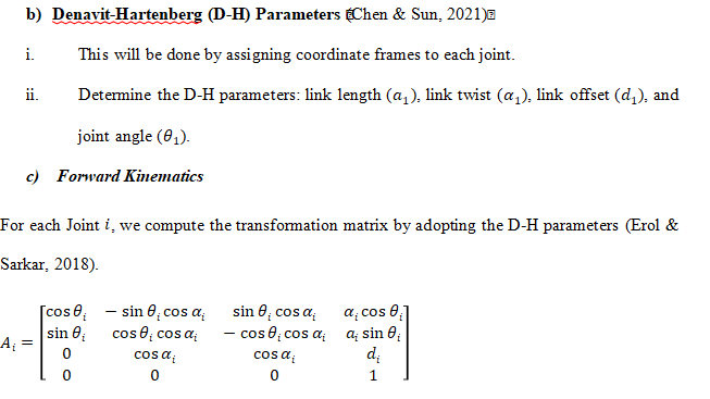
- Denavit-Hartenberg (D-H) Parameters (Chen & Sun, 2021)
- This will be done by assigning coordinate frames to each joint.
- Determine the D-H parameters: link length (
), link twist (
), link offset (
), and joint angle (
).
- Forward Kinematics
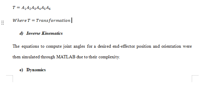
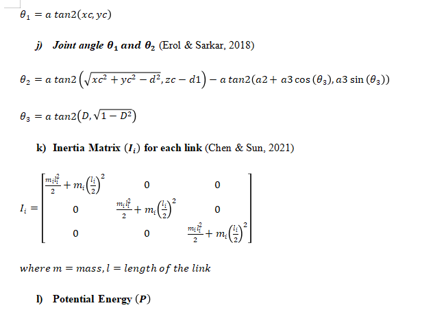
For each Joint , we compute the transformation matrix by adopting the D-H parameters (Erol & Sarkar, 2018).
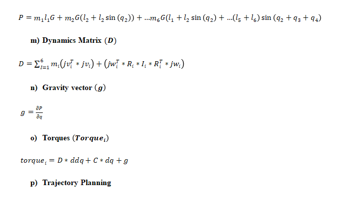
Technically, Trajectory planning involves determining the path that the manipulator’s end-effector will follow over time. This will be done within the MATLAB Code in the following stages;
- We shall define the start and end points, and any intermediate waypoints.
- We shall use polynomial equations, spline functions, or other trajectory generation techniques to define a smooth path.
- We shall ensure that the trajectory adheres to the dynamics and kinematic constraints of the system.
- Control
The control system ensures the manipulator follows the desired trajectory and reacts to disturbances. This will take the following steps and stages;
Control Algorithms
- It will begin with Proportional-Integral-Derivative (PID) control
- The code shall also be designed to handle the Control laws needed to account for the nonlinear dynamics of the manipulator.
Feedback Mechanism
- We shall also Implement encoders for feedback on joint positions and velocities.
- The Model shall also be designed such that it can use feedback to adjust control inputs for accurate trajectory tracking.
- Grapple Point Identification
In this model, the MATLAB Code is designed for capturing the Envisat satellite junk as follows:
- It will analyze the geometry and structure of Envisat to identify potential grapple points.
- It was designed such that it can choose a point that provides stability and minimizes the risk of damaging the satellite.
- Simulation
The Simulation was done in MATLAB and it tackles the following;
- It Modeled the manipulator, its dynamics, and the control system in the simulation environment.
- It also Tests the system’s performance in various scenarios to ensure reliability and safety.
- Results: ROBOT OUTPUTS
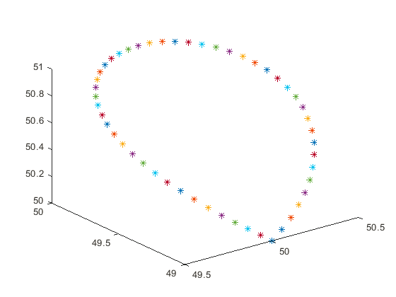
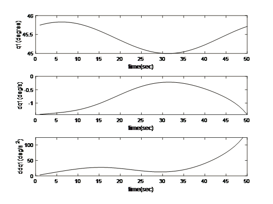
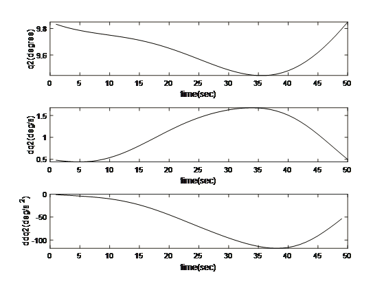
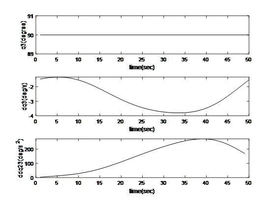
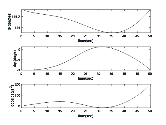
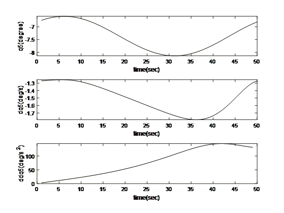
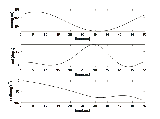
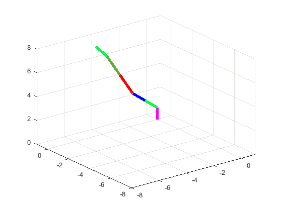
Motion and Trajectory Paths for the Kinematics
- Discussion and Conclusion
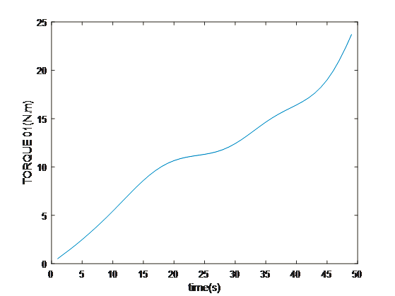
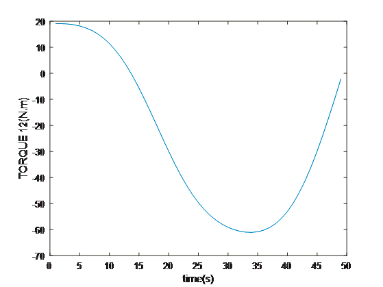
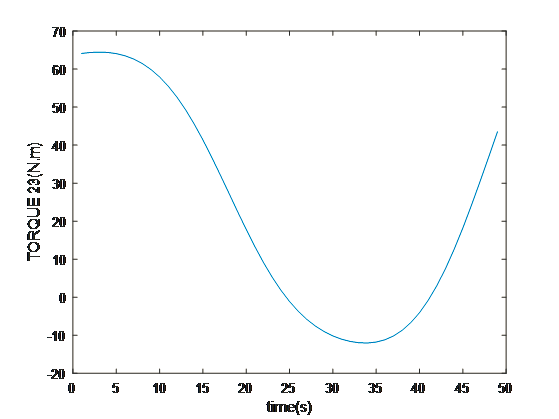
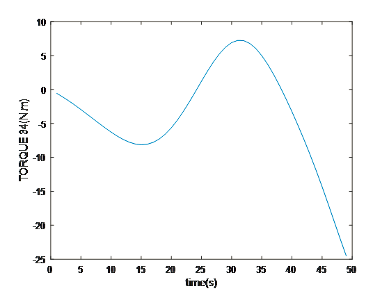
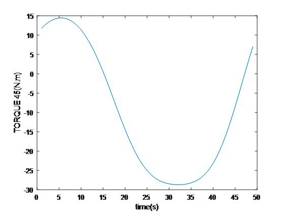
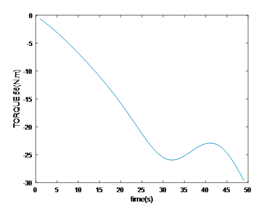
The multidimensional view of the operational dynamics of the robotic manipulator is given by an ensemble of plots generated from its simulation. These plots tell the story of every behavioral aspect related to joint trajectories and segment kinetics. They capture the delicate dance between movement and control mechanisms, emphasizing the synchronization necessary for articulated movements. This graphical data is very important to validate the robotic model against its specification and also optimize its functionality such that the manipulator can navigate complex spaces as well as dynamic environments in which it will operate. The torque profiles also emphasize the power finesse balance, which is vital for applications that include space debris capture where too much force can be just as harmful as having too little strength. On aggregate, simulated results reflect the theoretical and practical bases on which to transform a robotic arm from a concept into a real working machine that performs tasks with sufficient precision and reliability. This generalized visualization and analysis is a prerequisite for predicting and preventing potential issues, as well as preparing the arm to be deployed in complicated and merciless spaces such as space.
References
Chen, L., & Sun, H. (2021). Picking Path Optimization of Mobile Robotic Arm Based on Differential Evolution and Improved A* Algorithm. IEEE Access, 9, 154413–154422. Retrieved from https://scholar.google.com/scholar_lookup?title=Picking+Path+Optimization+of+Mobile+Robotic+Arm+Based+on+Differential+Evolution+and+Improved+A*+Algorithm&author=Chen,+L.&author=Sun,+H.&publication_year=2021&journal=IEEE+Access&volume=9&pages=154413%E2%80%
Erol, D., & Sarkar, N. (2018). Coordinated control of assistive robotic devices for activities of daily living tasks. IEEE Trans. Neural Syst. Rehabil. Eng, 16, 278–285. Retrieved from https://doi.org/10.1109/TNSRE.2008.922668