Question 1
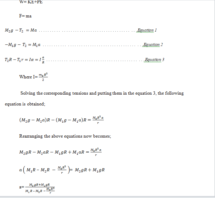
Acceleration is as follows;
W= KE+PE
F= ma
. . . . . . . . . . . . . . . . . . . . . . . . . . . . . . . . . . . . . . . . . . . .Equation 1
. . . . . . . . . . . . . . . . . . . . . . . . . . . . . . . . . . . . . . . . . . . . .Equation 2
. . . . . . . . . . . . . . . . . . . . . . . . . . . . . . . . . . . . . . . . . . . .Equation 3
Where I=
Solving the corresponding tensions and putting them in the equation 3, the following equation is obtained;
Rearranging the above equations now becomes;
=
a=
substituting the values in the above equations
= 7.9785
From equations of motion
=
= 478.7100
V= 21.8794m/s
The torque provided by the motor is as follows;
Tension on string
= Mg
= 1300 * ( 9.81 – 7.9785)
= 2381N
Torque = Fr
= 2381* 1.8
= 4285.8 N.m
Power from the motor
Time taken to attain 7m/s
t = (v-u)/a
=
= 0.8774 seconds
Power =
=
= 3.2564k J/s
= 32.564 kW
The gyroscopic procession torque of pulley
Radius of earth = 6,371 km,
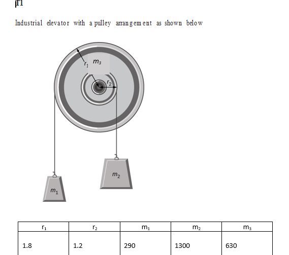
Total mass of system = m1 + m2 + m3
= 290 +1300+ 630
= 2,220 kg
Torque = F * r
= 2220*9.81* 6371000
= 138,748,912,200 Nm
Total torque = 138,748,912,200 Nm + 10785 N.m
=
This is in ant clockwise direction. The engineer should not be worried about this since the earth moves very slowly.
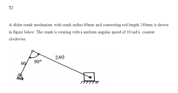
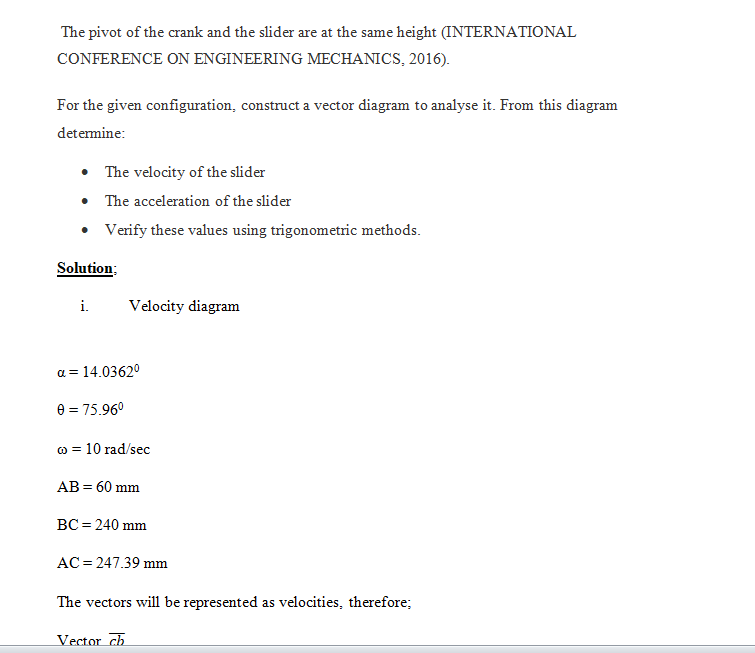
T2
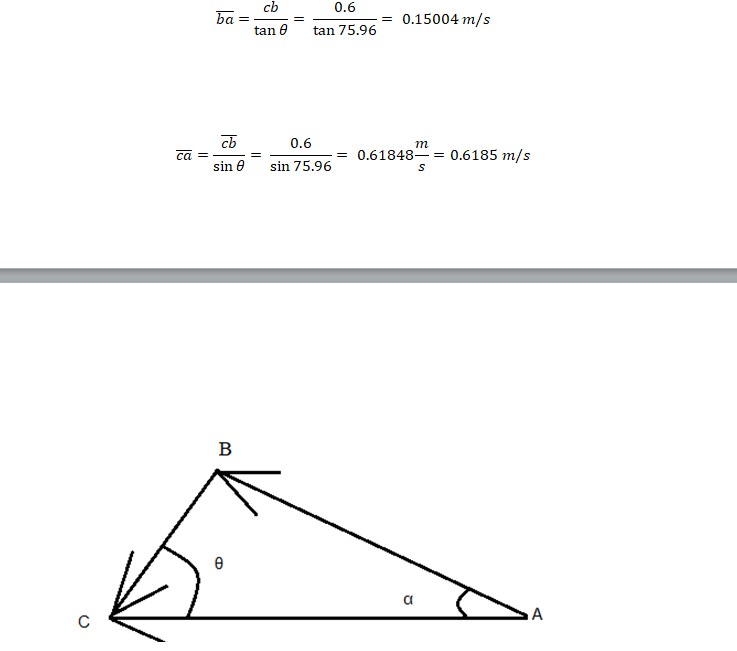
a. Velocity diagram
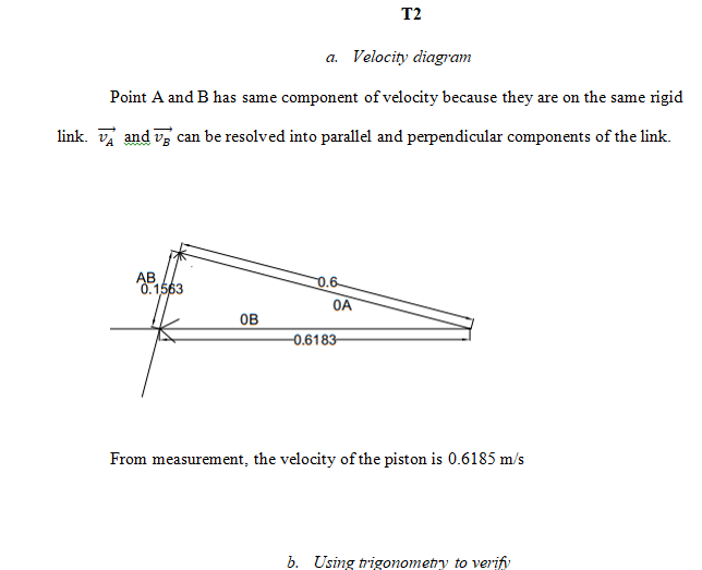
Point A and B has same component of velocity because they are on the same rigid link. and can be resolved into parallel and perpendicular components of the link.
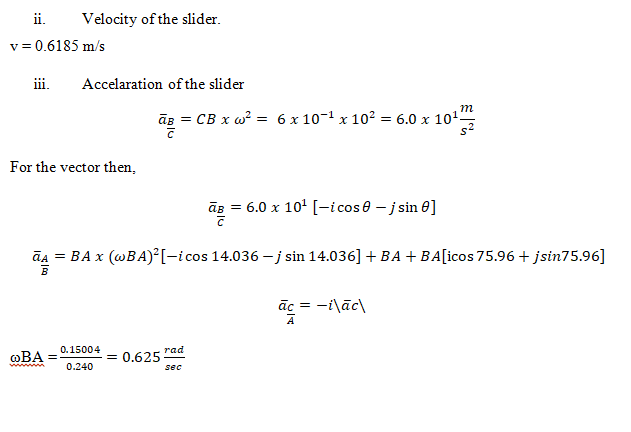
From measurement, the velocity of the piston is 0.6185 m/s
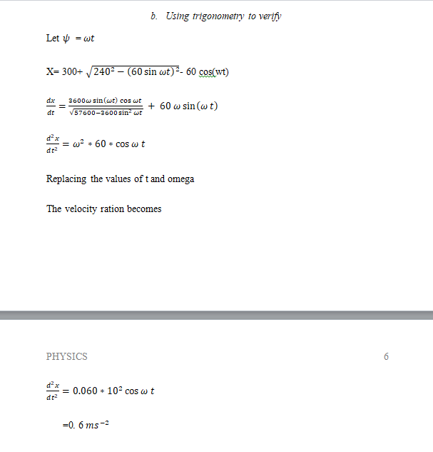
b. Using trigonometry to verify
Let =
X= 300+ – 60 cos(wt)
Replacing the values of t and omega
The velocity ration becomes
=0. 6
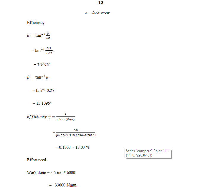
T3
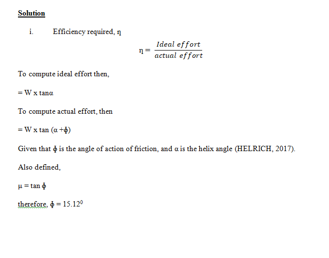
a. Jack screw
Efficiency
=
= 3.7076
=
= 15.1096
=
= 0.1903 = 19.03 %
Effort need
Work done = 5.5 mm* 6000
= 33000 Nmm
Work done by effort = 33000/ 0.1903
= 173410 Nmm
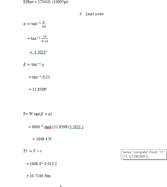
Effort = 173410/ (1000*pi)
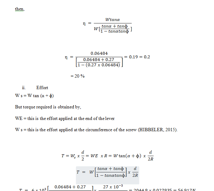
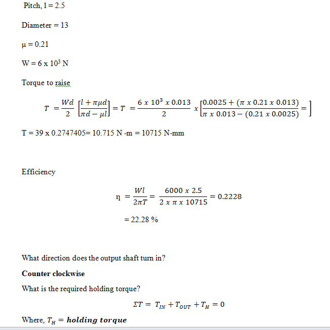
b. Lead screw
=
= 3.5021
=
= 11.8598
F= W tan
= 6000 * tand (11.8598+3.5021 )
= 1648.4 N
= 1648.4* 0.013/2
= 10.7146 Nm
=
= 22.28 %
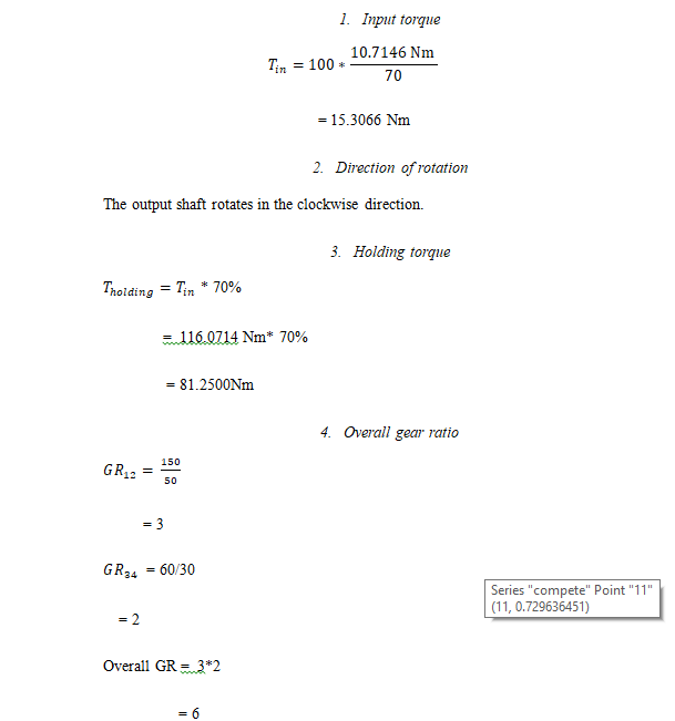
1. Input torque
= 15.3066 Nm
2. Direction of rotation
The output shaft rotates in the clockwise direction.
3. Holding torque
* 70%
= 116.0714 Nm* 70%
= 81.2500Nm
4. Overall gear ratio
= 3
= 60/30
= 2
Overall GR = 3*2
= 6
To connect the two shafts, a universal joint can be employed to keep a constant velocity ratio. For constant velocity ration, the sizes of the gear teeth and wheel has to remain unchanged.
5. Storage devices
Flywheel is a disc that is usually attached to the engine to smoothen the motion of the output motion from the engine. This device work by absorbing some energy during the peak periods and then the energy is used during the low peak periods to ensure constant velocity. The discs usually have considerable mass depending on the size of engine.
Among the advantages is that there is long life and temperature fluctuations does not affect the system. Disadvantages include power loss through friction and affected by air resistance as well.
T4
Gearbox manufactured of AISI 1045-H experienced premature failure after production. The shaft on the cross oil hole failed after it experienced a helical fracture making it not achieved the originally anticipated 100,000 cycles during the test after it was subjected to a cyclic testing with a frequency of 10 Hz. The fracture was due to fatigue. All sorts of methods were used to assess the cause and effect of the failure to avoid future failures. (https://link.springer.com/article/10.1007/s11668-017-0352-x?shared-article-renderer)
T5
The system is called mass spring damper system. Force vibration is the frequency mentioned above. External force with of known magnitude, a mass and a damper is used to form such system.. The other real-world application is in the building constructions where masses are hung in the middle of the building to absorb any vibrations.
a. Simple spring -mass system vibration
F= ma
Where m is mass and a is acceleration
In a spring mass the following equation holds
Ma = kx
m = kx
m + kx = 0 … . . . . . . . . . . . . . . . . Equation 4
Solving LHS
X= -0.5 + ;
=
so u now becomes
=
the solution of the above second order equation is
x= A + B sin . . . . . . . . . . . . . . . . . . . . . . . . . . Equation 5
dx/dt =B cos
. . .. . . . . . . . . . . . . . . Equation 6
So equation 4 becomes as follows when equation 5 and 6 and substituted in equation 4
2() +{ B cos }+ 8 ( A + B cos ) = 0.01cos(4t)
A= 0
9 Bcos t = 0.01cos(4t)
=0 .345
Combining the whole solution
U =
Period of forcing function = 2pi/4
Frequency of beats =
=
= –
Frequency of rapid oscillations =
=
= +
Plotting the homogeneous, particular and complete solutions
The homogenous solution
Particular solution
Differentiating homogenous equation and plugging it in equation of motion we have
Equating the sin and cosines in equation
Now let’s set coefficient equal.
cos(ωt):2mω0B=F0
⇒B=
Particular solution now becomes
For
The homogenous equation becomes
The complete solution is
X(t) = +
The plots are as follows;
b. Rotational spring -mass system vibration
Potential energy
U = mg d/2 (1- coso)
kinetic energy
Mechanical energy
(1)
Equation 1 now becomes
0 (2)
After rearranging (2) becomes
.
REFERENCES
Benenson, W. (2011). Handbook of physics. New York: Springer.
Urone, P. P. (2018). College physics. Pacific Grove: Brooks/Cole Pub. Co.
Choquet-Bruhat, Y., & DeWitt-Morette, C. (2019). Analysis, manifolds, and physics. Amsterdam: North-Holland.
Greenberger, D. M., Hentschel, K., & Weinert, F. (2019). Compendium of quantum physics: Concepts, experiments, history, and philosophy. Heidelberg: Springer.
- Final velocity using energy considerations as the elevator falls from its maximum lift height to ground level 30 m below.
Solution
So ……. kinetic energy conservation equation
Then; ………momentum conservation equation
Where m3 is considered as mass of the outer drum
Considering energy conservation equation
Then;
Putting the like term together
Considering momentum conservation equation
So
Putting the likes come together;
Thus;
So, considering resultant energy equation (MERIAM, 2015)
We get
Therefore;
Thus
Therefore
So to get the value of v1;
During a normal lifting operation, the elevator accelerates from rest to its operating speed of 7 m/sec over a distance of 12 m.
- Calculate the torque provided by the drive motor to produce this acceleration.
solution
First
Then torque
But
Thus torque
- Calculate the average power produced by the motor to give this acceleration.
Solution
Having radius of 1.2m
So
So angular velocity =
Therefore power;
Given that the pulley is mounted on the Earth and that the Earth is rotating with an angular velocity of 360 degrees per day it will be subject to a gyroscopic processional torque when operating normally.
- Calculate the size and direction of this torque. Should you as an engineer give this much consideration?
Solution
Here,
, Precession angular velocity
= 3600/24 hours
= 2π/ (24 x 3600 sec)
= 7.272 x 10⁻⁵ rad/sec
T = m g r
= 630 x 9.81 x 6.38 x 106 = 3.943 x 10¹⁰ N-m
Clockwise
For consideration, check for the gyroscopic effect (CLEGHORN, 2015).
I = 9.736 x 1037 kg/m2
Therefore,
rad/sec
This should not be given much consideration since the effect is negligible as evidenced by the precession angular velocity .
Verifying
a ̅(B/C)=6.0 x 〖10〗^1 [-i cos〖θ-〗 j sinθ ] a_n (BA)= ω_BA^2 BA =〖0.24 x 0.625〗^2 [-icos14+jsin14]=0.09375[-i0.97+j0.2419] a_t (BA)= O.24α_BA [icos75.96+jsin75.96]= O.24α_BA [0.2426i+0.97j] a ̅(B/A)=0.0923[〖-icos〗14.036+jsin14.036]+0.24αBA [icos〖75.96+〗 jsin75.96] a ̅_CA= a ̅(B/C)+a ̅_(B/A)= -14.5i-0.058j-0.08956i+0.02239j+〖58i(α〗_BA)+0.2329j〖(α〗_BA)
The y-component of the acceleration equals zero
And 4j = 0
-0.058+ 0.2329+0.2329α_BA=0
Therefore, α_BA=1.2349 rad/sec
ai ̅_CA=-0.0145-0.09+1.2349+0.58α_BA=0
α_BA =ai ̅_CA=0.513 m/s^2
The two values are close hence verified.
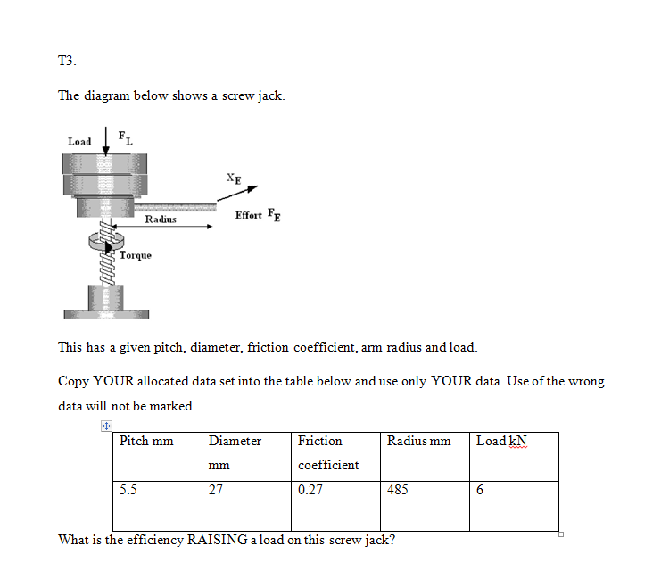
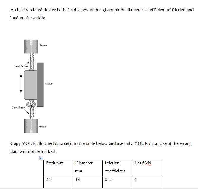
For your dataset, what is the torque required to raise the saddle load? What is its efficiency?
Your lead screw is to be driven by a small electric motor through the compound gear box shown below which is then coupled to the lead screw via a universal coupling drive shaft set up as a constant velocity one.
Gear A has 50 teeth, gear B 150, gear C 30 and gear D 60. Gear A rotates clockwise
Given that the efficiency of the gearbox is 70% what is the input torque?
What direction does the output shaft turn in?
What is the required holding torque?
What is the overall gear ratio?
Explain the conditions required on the drive shaft coupling to ensure that there is a constant velocity ratio between the gear box and the lead screw.
Other devices require the storage of energy whether for economic reasons or for high peak power conditions.
Research such devices, examine them and explain how they function, why they have been chosen for their particular application and any advantages/disadvantages they may have.
You should consider, as a minimum, devices such as spring devices, flywheel storage devices, pumped hydroelectric storage, compressed air storage and the hydraulic storage of Tower Bridge bascule operating mechanism.
T4
Research and examine a documented case of mechanical power transmission failure.
Create a short report summarising the failure which occurred and what was done to rectify the problem to reduce the likelihood of it recurring.
Solution
Failure of bearings in the transmission of power.
One of the main causes of failure in the bearings is the variable nature of forces which are obstinate by these bearings. The oscillatory nature of the loads which act on this given bearing lead to further growth of the cracks in the lower layers. The resulting cracks merge causing segregation of some tiny pieces of the materials from these surfaces. The pitting that is present on the surface is symbolical of the presence of Hertzian stresses. On the other hand, the Hertzian stresses are not cause for deformation in the bearings since these stresses manifest in almost all bearings (NGUYEN-SCHÄFER, 2016).
Upon, occurrence of pitting, there id reduction in the surface of the internal ring which is meant to endure the load. Consequently, there is an increase in surficial stresses. This leads to plasticity of this material in terms of its structure. Owing to the small nature of the surfaces that had been segregated by the Hertzian stresses, there occurs an increase in the contact between the internal rings and balls (QIU, 2017).
In order to reduce the possibility of failure the, the required measure to be undertaken is
- Application of the intermediate spring-damper configuration so as to reduce the magnitude of impact loads
The installation of a spring-damper configuration at the Cardan joint’s mid span can be used to remedy the effect of impact loading. This measure acts as a way of introducing a shock absorber and hence eliminates the loads which have large amplitudes (KHONSARI, 2017).
- Increase of the degrees of freedom so as to eliminate regularity in the impact forces.
To eliminate regularity, one more degree of freedom is added. This can be arrived at by the addition of another bearing into the system. This bearing will ensure free revolution and will therefore counter the effect of the deformations and enhance the life span of the joint (STEFANI, 2017).
T5.
Most mechanical systems can be subject to vibrations of one sort or another. In the simplest case of translational mass- spring systems and in rotational mass spring systems. Explain the usual form of these vibrations in both types of oscillation for small, un-driven oscillations. What is it called and what is the requirement of the system for them to occur?
All oscillatory systems have at least one frequency for which driven oscillations can be extremely large. What is this called? Identify the conditions needed for it to occur and measures that are taken to prevent this. You must explain the general principle behind the measures but should also detail at least 2 real-world instances where the principles have been applied and in what way.
A vibration isolation system for a console is modelled by the Damped spring system shown above. The mass is 2kg, the spring constant k = 8 N/m and the damping constant c= 1 N-s/m. It is being vibrated with a vibration force of F=0.01Cos(4t).
Solve the equation of motion Determine the amplitude and phase angle of the transient response. Plot the homogeneous, particular and complete solutions for the first 15 seconds using Excel and assuming it is stationary at x=0.015 when t = 0.
A 4kg slender bar length 2m is suspended from one end vertically and is free to swing WITH SMALL AMPLITUDE. Aerodynamic drag and friction on the pivot exert a resisting moment of magnitude 1.4 dθ⁄dt. Theta is measured from the vertical. A torsion spring also exerts a restoring torque of 8 Nm/radian If theta = 0.17 when t =0 and the bar is released from rest what is the resulting equation of motion?
A system undergoes free vibrations in the event that it oscillates only under an initial disturbing force with no external force(s) acting afterward. Some examples are the oscillations of a pendulum of grandfather clock, the vertical, oscillatory motion that is felt by a cyclist upon hitting a bump on the road, to add on this, the two simple mechanical vibrational systems are; translational-mass-spring system, rotational-spring system.
Translational spring mass system.
The usual form of vibration in translational motion is given in the figure below. The mass element when displaced by a small amount x, undergoes various forces indicated. The equation of motion can be written as,
mx ̈+cx ̇+kx=0
The general solution for the system
Rotational spring mass system
The usual form of the vibration in rotational motion is shown in the figure. The mass element when rotated by a small amount of θ, undergoes various forces as given. The equation of motion can be written as,
mθ ̈+cθ ̇+kθ=0
The general solution may be obtained by the substitution of the parameters of rotational vibration into the above solution.
Undriven system means a system without any eternal force on the system. These are referred to as free systems. For such systems to vibrate, the following three hold;
Kinetic energy storing element should be present
Potential energy storing element should be present, e.g. a spring
Energy dissipating device should be present.
Solution
m =
Considering moments about the pivot,
ΣM o = -Iα
-Iα =M+0.5mgsinθ
I_0=Iα+m(l/2)^2
= 〖ml〗^2/12+ 〖ml〗^2/4=〖ml〗^2/3
M+ Iα+m(l/2)^1 sinθ=0
Sin θ = θ since θ is very small
But;
α = (d^2 θ)/( 〖dt〗^2 )= θ ̈
M = 1.4θ ̇
〖4x 2〗^2/3 θ ̈+1.4θ ̇+〖4 x 9.81 x 2 〗^1/2=0
Equation of motion becomes
5.333θ ̈ + 1.4θ ̇ + 39.24 = 0
5.333θ ̈ + 1.4θ ̇ = -39.24
Bibliography
CLEGHORN, W. L. &. D. N., 2015. Mechanics of machines. Oxford: Oxford University Press. .
DELL’ISOLA, F. S. M. &. S. D. J., 2017. Mathematical modelling in solid mechanics.. s.l.:https://public.ebookcentral.proquest.com/choice/publicfullrecord.aspx?p=4822061.
HELRICH, C. S., 2017. Analytical mechanics. Cham: Springer.
HIBBELER, R. C., 2015. Engineering Mechanics Statics. Value Edition: Pearson College Div. .
INTERNATIONAL CONFERENCE ON ENGINEERING MECHANICS, &. F. C., 2016. Engineering mechanics. s.l.:http://public.ebookcentral.proquest.com/choice/publicfullrecord.aspx?p=4437517.
KHONSARI, M. M. &. B. E. R., 2017. Applied tribology bearing design and lubrication.. Hoboken, NJ : John Wiley & Sons Inc .
MERIAM, J. L. K. L. G. &. B. J. N., 2015. Statics. Hoboken, NJ: Wiley..
NGUYEN-SCHÄFER, H., 2016. Computational Design of Rolling Bearings. Cham: Springer International Publishing .
QIU, M. C. L. L. Y. &. Y. J., 2017. Bearing tribology: principles and applications.. s.l.:https://search.ebscohost.com/login.aspx?direct=true&scope=site&db=nlebk&db=nlabk&AN=1282152. .
STEFANI, F. P. A. R. L. &. F. R., 2017. Comparative Analysis of Bearings for Micro-GT: An Innovative Arrangement. Darji: Pranav H.; Bearing Technology; InTech .