Introduction
At the point when a flying machine travels through the environment there are numerous physical and concoction changes which happen around its surface. Be that as it may, if the speed is low enough, concoction changes are unimportant. To think about the physical changes over the air ship we take a cross segment of its wing and study them in a breeze burrow (Kumar et al., 2018).
In this examination, an unswept, untapered aerofoil with symmetrical segment is mounted in a transonic breeze burrow, in order to gauge the surface weight circulation. This is finished with various free-stream Mach numbers going from subsonic to supercritical. These estimations are utilized to evaluate the legitimacy of Prandtl-Glauret Law, which relates the weight coefficient at a point on the outside of an aerofoil in sub-basic, compressible stream to that at a similar point in incompressible stream.
At first, the weight coefficients are determined utilizing the deliberate surface weights. Which are then contrasted and the hypothetical weight conveyances anticipated by the Prandtl-Glauret Law (Lung, Goodhand and Miller, 2016). Utilizing the free-steam Mach numbers, the basic weight coefficient (Cp*) is determined and the basic Mach number (M∞crit) is likewise found.
Theory
Pressure Coefficient
At the point when the airfoil is situated in a free stream air, the speed of air over the upper surface increments while the weight diminishes and the other way around. The impact of changes in weight over a wing is basic in the investigation of streamlined features, as its properties exceptionally influence the flight. Weight is an impact which happens when a power is connected on a surface. It is the measure of power following up on a unit zone (Nickol, Mathison, Dunn, Liu and Malak, 2017).
Each point in a liquid stream field has its very own extraordinary weight, which is called weight coefficient, Cp. It is a valuable parameter for concentrate the stream of incompressible liquids, for example, water, and furthermore the low-speed stream of compressible liquids, for example, air.
This is given by the recipe;
Where:
P: Pressure at the point where weight coefficient is to be determined
P∞: Free stream weight
: Fluid thickness in freestream
: Freestream speed of liquid.
For compressible liquids, for example, air or rapid streams, the contrast among stagnation and static weight is never again an exact proportion of dynamic weight. Thus, weight coefficients can be more prominent than one in compressible flows.
Henceforth for compressible streams, the past recipe can be all the more advantageously re-written in the structure
(M∞ is the free-stream Mach number)
Mach number
Mach number is an amount which characterizes how rapidly a vehicle goes as for the speed of sound. The Mach number (M) is just the proportion of vehicle’s speed (V) isolated by the speed of sound at that height (a)
Where;
is the Mach number
is the overall speed of source to the medium and
is the speed of sound in the medium
Since it is characterized as the proportion of two speeds, it’s a dimensionless number. It is very subject to temperature and air arrangement. The Mach number is regularly utilized both with articles going at rapid in a liquid, and with fast liquid streams inside wind burrows (Zauner, De Tullio and Sandham, 2018).
For the most part the stream is isolated into five unique conditions:
Incompressible stream: M<0.3
Subsonic stream: 0.3
Transonic stream: 0.8
Supersonic stream: 1.2
Hypersonic stream: M>5
With the expanding Mach numbers stun waves are created and the temperature, weight, and thickness likewise increment.
The free stream Mach number of undisturbed stream, M∞, is identified with static/stagnation weights, P∞/Po∞, by the condition:
Transonic flow
A flying machine is known to be in transonic locale when the Mach number is between 0.8-1.2. It is the minute when the airplane is simultaneously beneath, at, or more the speed of sound (Nicolas et al., 2018). The transonic period is subject to airplane speed and the weight and temperature of nearby condition (Sugioka, Nakakita, Saitoh, Nonomura and Asai, 2018).
Transonic is a term utilized via flying machine creators to depict those high subsonic rates – as a rule above Mach 0.7 – where an air ship is going underneath the speed of sound however shockwaves are as yet present.
This precarious arrangement of stun waves prompts wave drag. It is the primary type of drag in transonic flights. At transonic and supersonic paces, there is a considerable increment in the absolute drag of plane because of essential changes in the weight dissemination. These physical changes incite stream detachment over the airplane surfaces.
The drag coefficient of plane is more noteworthy in transonic range than in the supersonic on account of whimsical stun arrangement and general stream hazards. Be that as it may, when a supersonic stream has been built up, the stream balances out and the drag coefficient is reduced.
One of essential changes that happen in the transonic district is the sudden increment in drag. The Mach number where drag of plane increases notably is called the drag-difference Mach number. Its esteem is regularly more prominent than 0.6; along these lines it is atransoniceffect and its esteem is likewise near, and constantly more noteworthy than, the basic Mach number. Normally the drag coefficient increments quickly at Mach 1 and starts to diminish at around Mach 1.2 when the stream movements to supersonic regime (Zauner, De Tullio and Sandham, 2018).
Procedure
- At first the barometric weight Pat in crawls of mercury was recorded.
- The manometer bank slant edge was set at 450.
- The injector weight Pj was at first set to 115 psi and the manometer readings were recorded, alongside climatic pressure(Iat), static weight (I∞), stagnation weight (Io∞), airfoil weight recordings (Watanabe, Azuma, Uzawa, Himeno and Inoue, 2018).
- The injector weight Pj was changed multiple times and distinctive readings were recorded at each esteem
- The readings taken in the manometer were all in inches, which were later on changed over to supreme weight.
Results and Discussion
| Date | ||
| Patm | 1015 | Moh Bar |
| Tatm | 16 | ⁰C |
| Manometer Angle (Ɵ) | 45 | Degrees |
Table 1: Raw Data
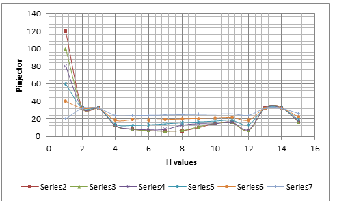
| Pinjctor Psi | Open Href1 | Open Href2 | H1 | H2 | H3 | H4 | H5 | H6 | H7 | H8 | H3A | Open Href3 | Hsta | Hstatic |
| 120 | 32.3 | 32.3 | 12.1 | 8.1 | 6.6 | 5.9 | 6.4 | 9.9 | 14.8 | 16 | 6.7 | 32.3 | 32.9 | 16.5 |
| 100 | 32.3 | 32.3 | 12 | 8 | 6.6 | 5.8 | 6.6 | 11 | 14.9 | 15.9 | 6.6 | 32.3 | 32.6 | 16.5 |
| 80 | 32.2 | 32.2 | 12.3 | 8.5 | 7.5 | 8 | 12.8 | 14.5 | 14.4 | 16.3 | 7.7 | 32.2 | 32.4 | 17.5 |
| 60 | 32.2 | 32.2 | 13.9 | 12.4 | 13.2 | 14.3 | 15.5 | 16.5 | 17.4 | 18.3 | 13.3 | 32.1 | 32.2 | 19.5 |
| 40 | 32.1 | 32.1 | 18.3 | 18.9 | 18.5 | 19.1 | 19.8 | 20.4 | 21 | 21.6 | 18.5 | 32.1 | 32.1 | 22.5 |
| 20 | 32 | 32 | 24.1 | 23.9 | 24.2 | 24.5 | 24.9 | 25.2 | 25.5 | 25.9 | 24.2 | 32 | 31.9 | 26.4 |
1) To change over the manometer perusing to total weight, following condition was utilized
Figuring the incentive for P1, for instance
P1 = 32.7 +/ – l12.8 – 33.2l sin (45)
Along these lines, P1 = 18.28 dad
The various weight readings were changed over to supreme weights as such.
2) To compute the free-stream Mach number, after condition was utilized
Computing M∞ at the injector weight 115psi,
M∞ = sqrt(2/0.4){(P∞/Po∞)^-(0.4/1.4) – 1
Along these lines,
M∞ = 0.82
Additionally, the other Mach numbers were determined
3) Pressure coefficient (Cp) was determined utilizing equation,
Utilizing the determined estimation of M∞, P, P∞ and substituting in the condition of Cp gives,
Along these lines,
Cp = 0.296
Different estimations of Cp were determined utilizing a similar equation.
4) The Prandtl-Glauret law weight coefficient (Cpc) were determined utilizing,
Where Cpi is the hypothetical weight coefficient in incompressible stream.
Substituting the qualities
Cpc = 0.396/sqrt (1-o.82^2)
Cpc = 0.6919
Different estimations of Cpc were determined correspondingly.
5) The condition used to compute basic weight coefficient (Cp*) was,
Computing for introductory Mach number for example M∞ = 0.82
Accordingly,
Cp* = 0.379
Staying five estimations of Cp* were determined utilizing comparable configuration.
As expressed already, transonic is a term utilized via flying machine fashioners to depict those high subsonic paces, where an air ship is going underneath the speed of sound yet shockwaves are as yet present. It typically is above Mach 0.7 (Rahman, Hasan, and Labib, 2015).
The wind current around a moving plane is considered to be incompressible at subsonic rates. The compressibility impacts have just minor consequences for the stream example and drag, up to a free-stream Mach number of about 0.7 to 0.8. The stream is subsonic all over the place. The neighborhood Mach number at the airfoil surface ends up higher than the free-stream Mach number in light of fact that the stream must accelerate as it continues about the aerofoil.
There in the long run happens a free-stream Mach number called the basic Mach number at which a supersonic point shows up close to the most extreme thickness. Showing that the stream by then has achieved Mach 1 (Placek, Miller and Ruchała, 2016)
Bigger locales of supersonic stream show up on the airfoil surface, as the free-stream Mach number is expanded past the basic Mach number and methodologies Mach 1. The stream must go through a stun so as to come back to subsonic stream from supersonic stream. This loss of speed is joined by an expansion in temperature, that is, a generation of warmth. This warmth speaks to a consumption of propulsive vitality that might be introduced as wave drag (Weiand, Michelis and Gardner, 2017).
From graphs of Cpexp Vs Cpthoery (Cpc), it was seen that the trial esteem correlates with the theoretical values for littler Mach numbers. In any case, as the Mach numbers expands the trial esteem and hypothetical qualities begin to stray. For the Mach numbers 0.38, 0.55 and 0.64 the charts nearly cover one another. In any case, for higher Mach numbers, for example, 0.76, 0.79 and 0.82 they vary with extraordinary sum.
This is mostly a direct result of expectation of Prandtl-Glauret hypothesis about the aerofoil being dainty. The hypothesis separates totally in super-basic stream, when districts of locally supersonic stream happen and stun waves begin to frame once again the outside of aerofoil. Though the hypothesis does not consider (Zauner, De Tullio and Sandham, 2018). Consequently when the basic Mach number is achieved, the hypothesis is of no significance.
Conclusion
In conclusion, the experiment aims were accomplished. The results of experiment bear cozy association with the hypothetical forecasts of Prandtl-Glauret law up to the basic Mach number (Mcrit). After which they exceptionally separate because of arrangement of stun waves. It was seen that because of arrangement of shockwaves there was a significant drop in the diagrams of Cp, and furthermore the area of shockwaves moved further downstream as M expanded. The investigation gave a superior comprehension of conduct of stream over the aerofoil in the transonic routine. There were a few mistakes in the test which included human blunders and some estimate of results. More precision in the outcomes would have been accomplished if the blunders referenced in the exchange were limited. At long last, despite the fact there was some blunder, the investigation was a triumph.
References
Kumar, R., Richardson, R., Gustavsson, J., Cattafesta, L.N., Kumar, R., Liu, Z. and Zha, G., 2018. Characterization of RAE 2822 Transonic Airfoil in FSU Polysonic Wind Tunnel Facility. In 2018 AIAA Aerospace Sciences Meeting (p. 0328)
Lepage, A., Dandois, J., Geeraert, A., Molton, P., Ternoy, F., Dor, J.B. and Coustols, E., 2017. Transonic buffet alleviation on 3D wings: wind tunnel tests and closed-loop control investigations. Advances in Aircraft and Spacecraft Science, 4(2), pp.145-167
Lung, H.W., Goodhand, M.N. and Miller, R.J., Rolls-Royce PLC, 2016. Aerofoils. U.S. Patent 9,453,416
Nickol, J.B., Mathison, R.M., Dunn, M.G., Liu, J.S. and Malak, M.F., 2017. Unsteady Heat Transfer and Pressure Measurements on the Airfoils of a Rotating Transonic Turbine With Multiple Cooling Configurations. Journal of Engineering for Gas Turbines and Power, 139(9), p.092601
Nicolas, F., Donjat, D., Micheli, F., Le Besnerais, G., Plyer, A., Cornic, P., Champagnat, F. and Michou, Y., 2018, June. Experimental study of a counter-flow jet in onera’s S1MA wind tunnel by 3D background oriented Schlieren. In ISFV 18
Placek, R., Miller, M. and Ruchała, P., 2016. The roughness position influence on laminar aerofoil aerodynamic characteristic in transonic flow regime. In Proceedings of the 30th Congress of the International Council of the Aeronautical Sciences (pp. 2-6)
Rahman, M.R., Hasan, A.T. and Labib, M.I., 2015. Numerical investigation of aerodynamic hysteresis for transonic flow over a supercritical airfoil. Procedia Engineering, 105, pp.368-374
Sugioka, Y., Nakakita, K., Saitoh, K., Nonomura, T. and Asai, K., 2018. First Results of Lifetime-Based Unsteady PSP Measurement on a Pitching Airfoil in Transonic Flow. In 2018 AIAA Aerospace Sciences Meeting (p. 1030)
Watanabe, T., Azuma, T., Uzawa, S., Himeno, T. and Inoue, C., 2018. Unsteady Pressure Measurement on Oscillating Blade in Transonic Flow Using Fast-Response Pressure-Sensitive Paint. Journal of Turbomachinery, 140(6), p.061003
Weiand, P., Michelis, S. and Gardner, A.D., 2017. Numerical Simulation of an Adaptive Wall in a Virtual Transonic Wind Tunnel. AIAA Journal, pp.3214-3218
Zauner, M., De Tullio, N. and Sandham, N.D., 2018. Direct numerical simulations of transonic flow around an airfoil at moderate Reynolds numbers. AIAA Journal, 57(2), pp.597-607