Introduction
One of the greatest dangers of cold weather flying is the in-flight icing that causes airflow disruption. During the movement of aircraft through the atmosphere, it experiences variation in the elements of weather including temperature, pressure among others. Part of this variation can be attributed to the geographical changes and variation in the altitude of the plane as it moves in the clouds. One of the effects of such variation is ice formation. The formation of ice on the aircraft has been a serious challenge to the aviation industry since time immemorial.
The formation of ice on the surfaces of the aircraft results from the flight through the clouds that have water droplets that have been supercooled (Lee 2017). When these supercooled water come into contact with the front facing of the aircraft including the propeller and tail, the thrust is lowered while the drag is increased. These occurrences results into unbalanced forces that act on the aircraft thus it becomes very difficult to have it controlled properly. The processes of super cooling are influenced by several factors including the ambient temperature, the size of the water droplets and finally the presence of the nucleating agents like dust. This basically implies that any approach used as part of the solution to this problem must take into account the above mentioned factors (Stolzer 2017). The shape and the amount of the accumulated ice on any part of the plane will be a function of the body shape and airfoil.
Methodology
Icing refers to the coating or deposits of an ice on an object. This is usually caused by freezing and impinging of liquid hydrometeors. There various types of ice that affects the aircraft including:
Types of Icing
Clear Ice
It is also called glaze. It refers to a heavy coating of a glassy ice that is formed when the aircraft is flying in those areas that have higher concentration of large supercoiled droplets of water such as cumuliform clouds as well as freezing rain. This kind of ice does not spread uniformly of the surfaces of the tails and the wings, antennas etc. This kind of ice is formed just a small section of the super cooled droplets of water that freezes upon impact. The temperature of the skin of the aircraft rises to 0 degrees with the heat being released during the initial freezing through the impact with portion of the droplet (MacLeod 2017).
This leaves a big section of the droplet is left to mingle and spread out with other droplets before it can finally and slowly. This leads to the formation of a solid form with no air bubbles embedded that can weaken the structure. As the ice continues to accumulate, it builds up into a double or single horn shape that projects ahead of the tail surface, wing ,antenna among others on which the collection is taking place. This kind of the formation of ice disrupts the airflow and therefore it is responsible for an increase in the quantity of drag by almost 300 to 500%.
The danger of this kind of ice is attributing to its effects which include the following:
- Loss of the lift which results from the altered camber of the wings and disruption of the smooth of air over the surfaces of the wings and tails
- An increase in the drag as a result of the enlarged area of the profile of the wings.
- The weight if the mass of the ice that is found on top of the aircraft
- The resultant vibration that is caused by the unequal loading on the sides of the propellers and wings. In case such masses of ice break off, they may results into the impairment of the plane structure.
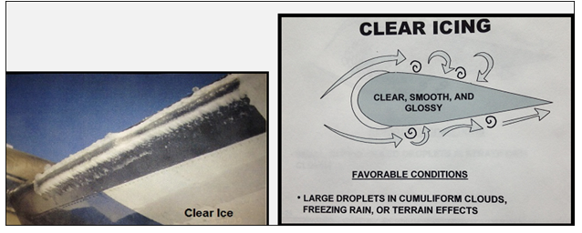
Figure 1: Clear Icing (Boyd & Stolzer 2016)
Rime Ice
This a milky or opaque deposit of ice whose formation on the plane is when it is flying through s strati form clouds This is usually dependent on the rate of catch of small super cooled droplets of water that takes place slowly. This ice accumulates on the leading edges of the antennas, pilot heads and wings. In order for this kind of ice to form, the skin of the aircraft must be at a temperature below 0 degrees (Boyd & Stolzer 2016). This will lead to quick and complete freeze of the drop without spreading out from the impact point. This implies that the droplets will retain their spherical shape as they continue to freeze. This allow for the creation of the air bubbles between the particles that are frozen. The results include ice with the irregular shape.
These deposits do not have much weight but it possess danger on the alteration of the aerodynamics of the wing camber. This ice also chokes the carburetor’s orifices and other instruments.
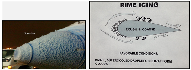
Figure 2: Rime Icing (Boyd & Stolzer 2016)
Mixed Ice
Just as the name suggests, this kind of ice possess the characteristics of the rime and clear icing. Small and large droplets of super cooled droplets do not exist. The appearance of this ice is whitish, rough and irregular in shape. The conditions that are considered favorable include frozen and liquid particles that are commonly present in cumuliform cloud as well as flakes of wet snow. Its formation combines the processes of those of rime and clear icing. Its accumulation is rapid and the removal is difficult.
Figure 3: Rime icing
(Boyd & Stolzer 2016).
Hoar
This is a semi-crystalline frost that is found on the surface of the aircrafts which is formed by the process of deposition in the clear air. Although it has very little effect on flight, it is known to obscure vision by creating a coated windshield. Its formation takes place in clear air when a cold aircraft enters a damper and warmer air during the steep descent.
Structural Ice
The rate of formation of ice on the surface e is actually affected by the shape of the components. When the wings can be made thin as for the case of the modern planes then the effects will be lowered as opposed to the thicker sections of the old wings. The rate of icing will be faster on the tail surfaces than the wings. The structural icing formation encompasses clear ice, hoar, mixed and rime icing on the structure of the aircraft component. In the event that aircraft tail stall as a result of ice accumulation, there is normally disruption of the airflow whose recovery may not be possible at lower altitude. Majority of the crashes have taken place as a result of such stalls (Gudmundsson 2013).
Type of Clouds and Icing
Cumulonimbus
There likelihood of icing occurring in the upper half of the clouds of cumulus as it approaches the stage of mature cumulonimbus. This is common when the temperatures are found between -25 degrees Celsius and 0 degrees. This favors the formation of clear ice. The formation of the ice is basically restricted to the shallow layer near the level of freezing and updraft region in mature cumulonimbus that is mature. To this extent, clear or mixed ice can be formed (Lee 2017).
Stratocumulus
The exposure of this cloud to icing is very common considering that it spreads out horizontally. Icing is common in cases where cumulus clouds are embedded in the stratus layer. Rime icing is very common in this type of clouds.
Large cumulous
This kind of clouds favors the formation of the clear ice especially on the upper super cooled surface.
Altocumulus
In case the cloud water content is high, icing in this type of cloud may be quite moderate. The icing is considered to be very light as and forms clear crystals thus clear icing.
Altostratus
This is one of the mid-level clouds that favor the formation of clear crystals on the lower section thus clear icing takes place predominately on the upper layer.
Nimbostratus
This is a low level cloud whose properties are of interest to the pilot. This kind of cloud is associated with the formation of hoar.
Fuel Induction System Icing
Induction icing refers to the building up of ice in the system of fuel induction and it is commonly known to affect all types of piston engine. This takes place as impact ice, throttle ice and fuel ice. The impact ice is formed by the impact of the moist air when the temperature is between -10°C and 0°C.Fuel induction icing forms at the downstream from the point that the fuel is being introduced at the carburetor at it occurs between the temperatures of +4°C to +27°C.
De-icing and Anti-icing
The aircraft De-icing and Anti-icing steps are usually used to achieve their goals:
- Removal of semi frozen or frozen moisture from the critical external surfaces of the plane on the ground before flight
- Protection of the aircrafts surface from such contaminants for the treatment period hence becoming airborne.
- Removal of semi frozen or frozen moisture from the intakes of the engine and the fan blades prior to the takeoff times
At the initial stages, the aircraft is undertaken through an inspection program to check for the signs of any contaminants adhering to the surface. Any icing element is removed by the use of the deicing chemicals (Lee 2017). The assessment of the prevailing weather conditions is also very important. In case there is an anticipation of the adherence of ice during the flight, there is usually an application of the suitable anti-icing fluid. These particular fluids have been designed to shear off the surfaces of the aircraft from the icing effects.
About Tail Stall
The stabilizer that is horizontal tends to balance the nose so as to pitch down through the generation of downward lift on the aircraft’s tail. During the stalling of the tail, there is a reduction of the downward force (Boyd & Stolzer 2016). This leads to severe pitch down of the nose. Considering that the plane’s tail has a smaller leading edge radius and length of the chord as opposed to the wings, it collects more ice than the wings. The worst cases are that the accumulation of the ice is not seen by the pilot himself.
Wing Stall
The stalling of wings will take place at a lower attack angle leading to a higher speed when there is ice contamination. This basically implies that even a very small amount of ice will have a significant impact and the effect may be worse when the ice becomes rougher. This basically implies that the approach speed should increase in case ice particles remain on the wings for a long time.
Related Accidents of Icing Airframes
First incident
In the year 2018 on 12 April, a Piper PA-24 airplane, N7386P, was actually forced to land near New Braunfels, Texas. The instructor of the flight and pilot received minor injuries. During the process of landing, the plane was damaged substantially. The pilot reported he had been preparing for the commercial check for the ride with his instructor. The plane was configuring for landing but felt and heard what seemed like the engine was undergoing a gradual retardation for landing. Consequently, there was an occurrence of unintentional execution above the cleated level. Upon the recovery from this effect, it was discovered that re-engagement of the AP system was not possible.
The Vibration of the engine started and the declaration of PAN was done using CPDLC leading to the diversion to Singapore(Olsen, Wuebbles & Owen, B. (2013) The engine, however, remained in use and the effects of the vibration stopped during the descent with the other diversion being uneventful other than the need to dump fuel and set manual flight mode.. The investigation revealed that the cause of the vibrations was the ice or water crystals that were actually entering and passing through the system of the spinner. These components faired and accreted as ice under the annulus fillers making the aircraft to be out of the situation of balance. There was continuation of this vibration effect even as the ice continued melting.
Information of the pilot
- Age: 28
- Occupied seat: Left
- Ratings of instructor: None
Flight instructor information
- Certificate: Commercial
- Age: 25
- Ratings of instructor: Single engine aero plane
- Occupational pilot: Yes
Information of Aircraft
- Manufacturer: Piper
- Manufacturing year: 1961
- Type of landing gear: Retractable
- Engine type: 1 reciprocating
- Propeller: 3-bladed propeller.
Second Incident
In the year 2018 on 9 April a PIPER PA-24-260 airplane, N9456P, was thoroughly destroyed after collision with the terrain and trees. The craft lost pressurization of the cabin in the flight and the emergency descent was actually completed before the original flight could be continued at a relatively lower level. The area of the crash is characterized by very low temperatures. This allowed for the freezing of water within the transducers of pressure. The investigation revealed unequal melting of ice from the components leading to stalling. The condensation process was gradually non-uniform. Actually it was discovered that even in the case of a new version of such planes, water can possibly condense within the transducer. Its subsequent freezing interferes with the bleed system for measurement of pressure (Torenbeek 2013).This became the basis of investigation of the effects of icing on pressure balance.
Information of the meteorology
- Condition at the scene of accident: Visual conditions
- Dew point /Temperature: -5 degrees Celsius.
Impact information
- Injuries of the crew:2 injuries instructor and pilot
- Passenger injuries: 4 fatal
Aircraft information
- Manufacturer: PIPER
- Type of landing gear: Retractable
- Engine type: Single engine
- Propeller: 3-bladed propeller.
Third Incident
In the year 2009 on October 16 PC-12 took off from Budel runway at around 08:22.The pilot got instruction to make a left turn just after it had taken off before proceeding to Osgos. During the left hand climbing turn, the operations were still okay until a significant height was attained. When the plane was in the clouds, the system of auto piloting disengaged. The altitude was quickly lost and the plane could not be traced. The reports by the NTSB indicated that the Colgan Air was inadequate for the selection of the airspeed as the icing conditions approached (Schatz et al.2016). The accumulation of ice on the aircraft’s surface resulted into the development of moisture in the engine thus auto piloting system disengaged. This was treated to be one of the probable causes of the accident. The plane was actually equipped with the systems of the ice detection on its wings, tails, and propellers. The parameters of the ice detection were actually programmed to indicated detection whoever there was an accumulation of ice.
Impact information
Crew injuries: 2 fatal ones, pilot and the instructor.
Aircraft information
- Type of engine: Single
- Number of propellers: 4
Conclusion
In conclusion, it is persuasive to believe that majority of the aircraft accident are caused by icing effects. Although some of these incidents and accidents might have not been recorded, the studies have revealed significant impact of icing on the aircraft operations. It is feasible for carburetor ice to frame notwithstanding when the skies are clear and the outside air temperature is as high as 90 degrees Fahrenheit if the relative dampness is 50 percent or all the more especially when engine rpm is low. This is the reason when flying most planes with the carbureted engine; understudies are bored to turn on the carburetor heat before making a huge power decrease.
Carburetors can also ice up at voyage control when flying in clear air and in mists. The envelope for the most extreme developments of carburetor ice is between 60 what’s more, 100 percent relative moistness and 20 to 70 degrees Fahrenheit. At the principal sign of carburetor ice, apply full carburetor warmth and LEAVE IT ON. The engine may run rougher as the ice dissolves and experiences it, be that as it may, it will shed out once more(Wiegmann & Shappell 2017).The engine rpm should come back to its unique control setting. On the off chance that the rpm drops once more, flight with the carb heat on will be recommended.. In any case, at the point when conditions are good for auxiliary ice, fuel injected motors can lose control and even fizzle if the air channel and admission entries are hindered by ice (Torenbeek 2013).
REFERENCES
Blickensderfer, E. L., Lanicci, J. M., Vincent, M. J., Thomas, R. L., Smith, M., & Cruit, J. K. (2015). Training general aviation pilots for convective weather situations. Aerospace medicine and human performance, 86(10), 881-888.
Boyd, D. D., & Stolzer, A. (2016). Accident-precipitating factors for crashes in turbine-powered general aviation aircraft. Accident Analysis & Prevention, 86, 209-216.
Gudmundsson, S. (2013). General aviation aircraft design: Applied Methods and Procedures. Butterworth-Heinemann. 10, 33-56
Knecht, W. R. (2013). The “killing zone” revisited: Serial nonlinearities predict general aviation accident rates from pilot total flight hours. Accident Analysis & Prevention, 60, 50-56.
Lee, A. T. (2017). Flight simulation: virtual environments in aviation. Routledge24 ;5-26.
MacLeod, N. (2017). Building safe systems in aviation: A CRM developer’s handbook. Routledge. 66, 52-58
Olsen, S. C., Wuebbles, D. J., & Owen, B. (2013). Comparison of global 3-D aviation emissions datasets. Atmospheric Chemistry and Physics, 13(1), 429-441.
Patankar, M. S., & Taylor, J. C. (2017). Risk management and error reduction in aviation maintenance. Routledge 13(1), 29-44.
Schatz, S. P., Schneider, V., Karlsson, E., Holzapfel, F., Baier, T., Dörhöfer, C., … & Mumm, N. C. (2016, November). Flightplan flight tests of an experimental da42 general aviation aircraft. In 2016 14th International Conference on Control, Automation, Robotics and Vision (ICARCV) (pp. 1-6). IEEE.
Shappell, S., Detwiler, C., Holcomb, K., Hackworth, C., Boquet, A., & Wiegmann, D. A. (2017). Human error and commercial aviation accidents: an analysis using the human factors analysis and classification system. In Human Error in Aviation (pp. 73-88). Routledge.
Stolzer, A. J. (2017). Safety management systems in aviation. Routledge13(1), 42-44
Torenbeek, E. (2013). Synthesis of subsonic airplane design: an introduction to the preliminary design of subsonic general aviation and transport aircraft, with emphasis on layout, aerodynamic design, propulsion, and performance. Springer Science & Business Media56(10), 81-88.
Wiegmann, D. A., & Shappell, S. A. (2017). A human error approach to aviation accident analysis: The human factors analysis and classification system. Routledge. 46(10), 41-44.