Introduction
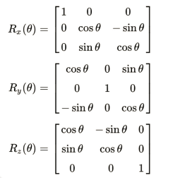
In linear algebra, an object in Euclidean space can be turned using a transformation matrix called a rotation matrix. Using the format below as an example, the matrix
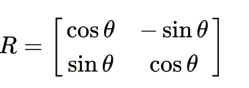
The points on the x and y axes were moved anti-clockwise by an angle of θ that is relative to the starting point of the Cartesian coordinate that is 2D and to complete this motion that is rotationary on the point on the plane that is with the standard coordinates v = (x, y) then Multiply the column vector that will describe the rotation by this R matrix.
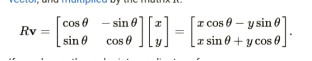
If the coordinates in the endpoint of the vectors are at both the x and y in which the x is represented by cos and y is given by the sin then equations mentioned earlier is then going to be transformed into the formulas that will be given by the process of the trigonometric summing of these angles and we think of the formulas for the trigonometric summation of angles as a matrix representation of these rotation matrix and a way of thinking about it is wishing to rotate the vector which is at 30° off the x-axis by 45° then discovering that its terminus there artat 75 degrees is all that’s required.
This examples will seek to ensure on the focusing on the rotations that were active of these counterclockwise vectors via the coordinate system that was right-handed which is y counterclockwise from x prior to multiplication and the R which is to the left and the inverse and transpose of the example matrix has to be used in this event or that either of these are altered.
The zero vectors and the coordinates of the origin are unaffected by matrix multiplication, which is why rotation matrices display rotations around the origin. Geometry, physics, and computer graphics calculations often make use of rotation matrices, which algebraically express these rotations. A lot of academic journals classify improper rotations as “rotation” and label them as symmetrical matrices where the determinant is negative one (rather than +1). Reflections, which invert orientation, and suitable rotations are part of them. When reflections are ignored, the correct label could be missing in other cases. This piece follows the second school of thought.
Background
These matrices for the Rotation are the matrices with a square shape with entries that are real and the matrices that are orthogonal with determinant 1 is described precisely when it is a square matrix R which is a rotation matrix if RT that is equal to R−1 and det R which is is equal to 1 and an example of this special orthogonal group is the group of the rotation represented already by SO (3) that is defined by all these matrices that are orthogonal of the size n with determinant of +1 and the orthogonal ordinary group O (n) is this collection of all the n-dimensional matrices that ate orthogonal which are having a determinant of either +1 or −1.
As a change which moves these locations whilst also keeping all their consecutive distances constant from one another and this rotation is an example of an isometric in Euclidean geometry. Other than maintaining “handedness” while leaving (at least) one point fixed, rotations differ from other isometrics in two further ways. As an illustration, a reflection flips the left and right ordering, a translation transfers all points, an inappropriate rotation combines a handedness shift and a standard rotation, and a glide reflection performs both.
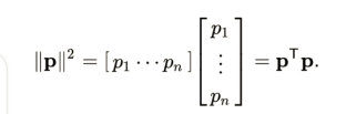
After a point that is fixed is recognized as being the origin then every point in this coordinate system of this Cartesian has its coordinates that are consecutive whilst being given to it as a displacement from this mean origin and the vector space of displacements may be used rather than actual locations then on assuming that this coordinates of the p which moves from the origin O to point P are (p1… pn) then now on Selecting the basis that is orthonormal suc
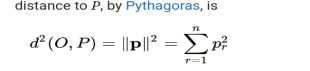
coordinates Pythagoras’ squared distance to P =
This is calculable using multiplication of matrix
Geometric rotation is a technique that turns lines into lines while preserving point-to-point distance ratios. These properties show that a rotation can be written as Qp, the matrix form, because the vectors have undergone a linear transform. It can be stated as follows: The assertion that a rotation maintains ratios and distances themselves
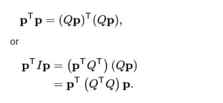
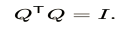
Every rotation matrix, Q, satisfies the orthogonality criterion since For every vector, p, this equation is valid.
Because rotations are unable to alter the axes’ ordering, which necessitates the unique matrix condition, handedness is preserved.

Moreover, it may be demonstrated that any matrix meeting these two requirements functions as a rotation.
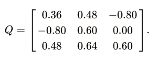
Examine the rotation matrix of 3 × 3.
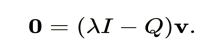
If Q only acts as a scaling by a factor λ and acts in a given direction, v, and then we get

So that;
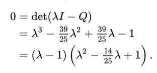
This means that λ is a polynomial root for Q
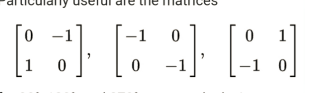
Two key points which are standing out where on the first place we see that the fact that 1 is an eigenvalue turns out to show that the matrix is not affected by any of these in any direction in particular and whilst talking about these rotation ,movements in these three dimensions this is the axis which matters and this word has no significance when it is applied to the dimensions in the lower planes while the two remaining roots are usually made up of complex conjugates which are in number and 1 for the term that is constant for the quadratic and 2 cos θ for the term that is linear which was negated and one of the most intriguing aspect of these is that it occurs for all 3 × 3 rotation matrices and the rotation which is we see that the conjugates that are complex which is 1 while when it is for a 180° rotation they are -1. The factorization of every n × n rotation matrix is also comparable. For all dimensions (under the two conditions given), the residual polynomial factors into terms like this one. A “dangling” eigenvalue of 1 will exist if n is an odd dimension. A degree of n and n eigenvalues are guaranteed for the distinctive polynomial and it moves with the transpose and is a matrix that is normal and a matrix of the rotation is diagonalized and assuming that the coordinate system was correct where we discover that any rotation matrix may be expressed as a partition of two-dimensional subspaces into individual rotations of no more than n/2 dimensions.
The trace which is defined as the addition and the entries were summed up which were on this diagonal in this principal of this that is similar to total of it’s the eigenvalues even when not similar to the orientation of this systems of coordinates. The fact it shows angle of rotation θ in this 2D space or even the subspace is conveniently indicated in 2 × 2 and 3 x 3 rotating matrices. The trace of a 2 × 2 matrix is 2 times the cosine of θ, while the trace of a 3 × 3 matrix is 1 plus 2 times the cosine ofΠθ. Vectors having an eigenvalue of 1 and oriented perpendicular to the rotation axis make up the subcategory in the three-dimensional instance. Therefore, we can determine if the rotation is complete by taking the axis of rotation and angle from any 3 × 3 rotating matrix.
Method
Vector rotation in two dimensions is counterclockwise for positive θ for R(theta), however for θ (such as −90°) it is clockwise. It has been so decided that the clockwise rotation matrix is:
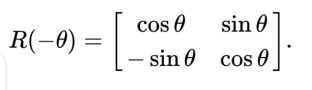
The sole case when the rotational vectors group is commutative and not irrelevant, meaning it is not a single-dimensional is when, where it makes no difference in the order in which numerous rotations are carried out—is the two-dimensional in nature case. A different convention makes use of rotating axes, and the aforementioned matrices likewise show them rotating through θ in a manner that is clockwise.
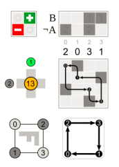
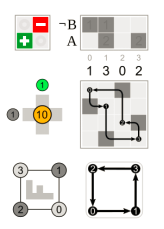
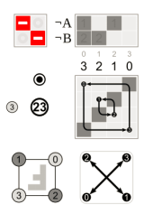
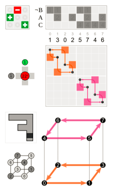
Fig 1: rotation on standard axes passing on theta
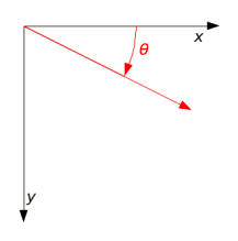
The R(θ) is anticlockwise when using the standard x- and y-axes in a right-handed Cartesian coordinate system are pointed up and to the right, respectively and this is clockwise for a left-handed coordinate system in which the points in the points below and its y-axis runs the width of the screen or page and the origin is placed in the top left corner; nevertheless, non-standard orientations are not uncommon in two-dimensional computer graphics, even though they are rare in mathematics.
Listed below are additional conventions that may alter the perception of rotation generated by a set of the matrix of rotations.
Specifically we see that they are helpful.
Where the – 90° which is the positive 270° rotation on the right is equivalent to two 180° which is at the centre and one 90° left rotations and a permutation’s matrix representation where are centre right and these additional relevant diagrams, and the rotation with respect to the initial position that is bottom left are all shown in each of these images.
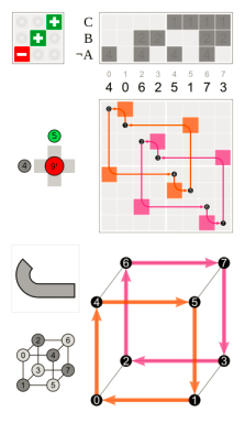
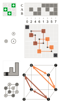
Frameworks for three-dimensional rotation
Following a 90-degree rotation with respect to the left y-axis, one can turn 120 degrees across the major diagonal (right) by circling the centre z-axis.
The rotation matrices are at the top left corner, and the corresponding cube permutations with the
origin in the middle are in the bottom right.
A simple three-dimensional rotation, commonly referred to as an elemental rotation, revolves around one of the coordinate system’s axes. Vectors in three dimensions can be rotated and the right-hand rule is used to calculate an angle Δ around the x-, y-, or z-axis, therefore codifying their alternate signs. The following are the three rotation matrices.You’ll see that the application of the right-hand rule is limited to multiplication by R.x. (The same matrices can also be used to rotate the axes clockwise.)
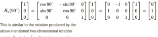
When the axis around which a column vector rotation occurs points in the direction of the viewer,The angle θ is positive, and the coordinate system is right-handed , all of these fundamental vector rotations seem counterclockwise. It is simple to verify that Rz, for example, would be rotatingin the axis of y direction a vector that is parallel to the the axis of x by using Rz on the vector (1,0,0):
Matrix multiplication is used to get additional 3D rotation matrices from these three where the end result stand for the set of rotations with α, β, and γ as the yaw and pitch and also the roll angles which are corresponding one to one. Around the z-, y-, and x-axes, respectively, the Tait-Bryan angles α, Η, and γ formally characterize the intrinsic rotation.
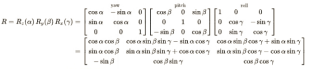
Comparably with this item:
symbolizes an external rotation around the axes x, y, and z, with (improper) Euler angles of alpha, beta, and gamme.
Because matrix multiplication is generally non-commutative, these matrices only have the desired effect when pre-multiplying column vectors in the prescribed order. Rotation operations are carried out to the from the given directions that is beginning with this for distribution that is opposite to the vector and moving its left.
Fig 2: It is possible to deconstruct the rotation R about axis u via the three endomorphisms P, (I − P), as well as Q.
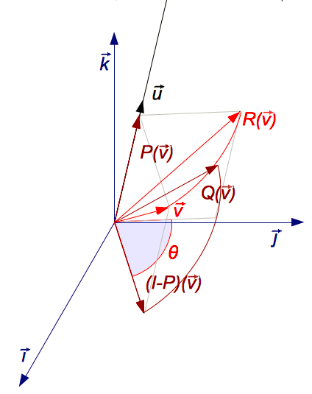
There is only one real eigen vector in a three-dimensional general rotation matrix, up to a multiplicative constant that corresponds to the eigenvalue λ = 1. This means that since u must produce u when rotated around the rotation, the equation Ru=u must be satisfied by a vector that is perpendicular to u in the axis of rotation when given a marix of 3 × 3 rotation. Up to a scalar factor, the above equation which is solved for u that is unique unless R is equal to I and the eigenvector u of R has the eigenvalue λ = 1, unless stated differently.
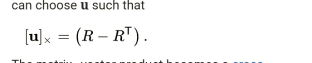
In order to guarantee that the outcome is zero, the matrix-vector product is transformed into a vector’s cross product with itself:
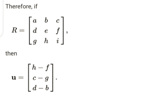
This method yields ‖u‖ = 2 sin θ, the magnitude of u, where θ is the rotation angle.
Conclusion
Together with reflection, translation, and dilation, there are four different geometric transformations: rotation. An object rotates when it is turned about a specified point in a clockwise (negative) or counterclockwise (positive) direction. The item is known as the pre-image, and the original object is following that rotation is called the image. For rotations of 90, 180, and 270 degrees clockwise and counterclockwise about the origin, there are broad guidelines. A geometric figure rotating around a point is called a rotation. Degrees are used to describe the amount of rotation. The rotation is done clockwise if the degrees are negative, and counterclockwise if they are positive. The figure will change direction instead of size or shape, unlike a translation. The first figure is always referred to as the pre-image, while the rotated figure is referred to as the image.When rotating an object, there are several general guidelines, that apply in employing the most widely used degree measurements—90, 180, and 270 degrees. When rotating an item by ninety degrees, the usual rule is (x, y) ——–> (-y, x). By taking the points of each vertex, translating them in accordance with the rule, and generating the picture, you can use this rule to rotate a pre-image. Consider the preceding illustration: the pre-image’s ends are indicated by the points (1, 1) and (3, 3). The end points of the image will be (-1, 1) and (-3, 3) when you rotate it using the 90-degree rule.
References
Aggarwal, C. C., Aggarwal, L. F., & Lagerstrom-Fife. (2020). Linear algebra and optimization for machine learning (Vol. 156). Springer International Publishing.https://link.springer.com/content/pdf/10.1007/978-3-030-40344-7.pdfFarin, G., & Hansford, D. (2021). Practical linear algebra: a geometry toolbox. Chapman and Hall/CRC.https://www.taylorfrancis.com/books/mono/10.1201/9781003051213/practical-linear-algebra-dianne-hansford-gerald-farinStrang, G. (2022). Introduction to linear algebra. Wellesley-Cambridge Press.https://epubs.siam.org/doi/pdf/10.1137/1.9781733146678.fmWang, S., Hu, Y., Wang, Q., Wu, B., Shen, Y., & Carr, M. (2020). The development of a multidimensional diagnostic assessment with learning tools to improve 3-D mental rotation skills. Frontiers in Psychology, 11, 305. https://www.frontiersin.org/articles/10.3389/fpsyg.2020.00305/fullYang, X., Zhou, Y., Zhang, G., Yang, J., Wang, W., Yan, J., … & Tian, Q. (2022). The KFIoU loss for rotated object detection. arXiv preprint arXiv:2201.12558.https://arxiv.org/abs/2201.12558