Introduction
Global Tech Corp. is a rapidly expanding firm that provides sophisticated technology packages. It recently tried to implement an automated inventory management program to help with warehouse operations. However, the implementation failed because poor system design and lack of a thorough analysis occurred. This failure resulted in waste, financial losses, and customer unhappiness. To prevent such similar problems, the company needs a sound method to design and build systems (Adzgauskaite et al., 2025).
A proposed new inventory management system will help optimize operations, eliminate errors and make sure the warehouse runs smoothly. The system will have user registration and login, manage purchase of products, sales and purchase reports, payment processing and good sales tracking. These will assist administrators and customers to make informed decisions utilizing real-time information.
The project will adopt the Agile methodology which includes the ability to adapt, receive continuous feedback, as well as, iterative development. Agile will enable the team to rapidly respond to change, increase productivity, and result in a quality system. Development process will include planning, design, coding, testing, and deployment in short iterations. Contact with stakeholders will see that needs are met. By adopting this methodology, the new inventory management system will be reliable, flexible and intuitive – meeting the company’s needs in the efficient way (Aratchige et al., 2024).
1. Planning, Requirements Modeling, and Analysis
1.1. Scope Identification and Project Planning
The project is to design and implement an inventory control system for Global Tech Corporation. It includes functionalities like user login, product management, purchase and sales tracking, payment handling and report display. The new system will help to improve efficiency, minimize mistakes, and facilitate smooth warehouse operations. Agile methodology will be employed to build the system incrementally and iteratively allowing for ongoing refinement and stakeholder feedback (Day, 2025).
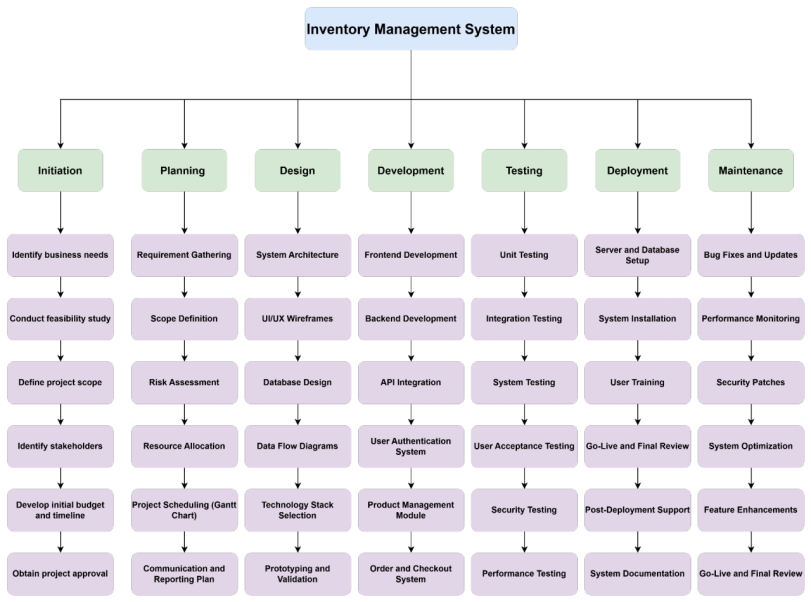
Work Break Down Structure
A Work Break Down Structure (WBS) assists in breaking tasks down into smaller, manageable pieces. It breaks down the project into broad phases like planning, design, development, testing, and deployment. Each phase is then detailed into individual tasks.
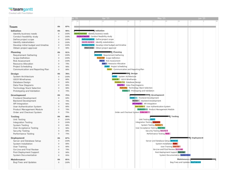
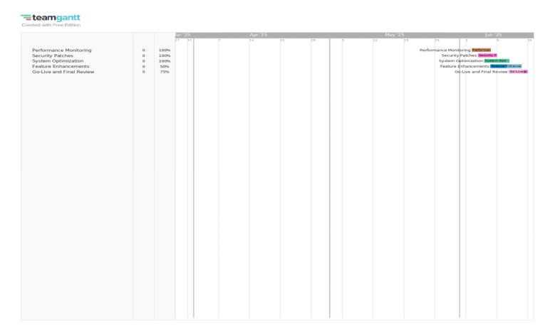
The Gantt Chart
The Gantt Chart is task scheduling based on Agile method. It sets up start and end dates for each task, ensuring project deadlines are achieved. The chart provides a clear visualization of dependencies among tasks to assist in resource allocation and tracking the progress.
1.1. Use Case Modeling
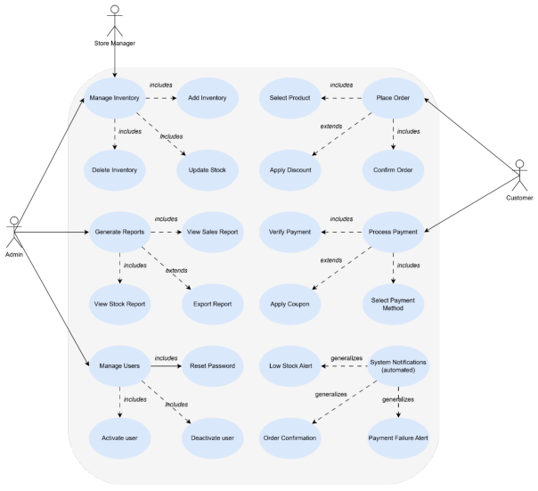
Use case diagram
A Use Cases Diagram shows the way the various actors interact with the system. The diagram shows the main functions of the system and the roles of users in these functions. For an Inventory Management System, the actors may include Administrators, Store Managers and Customers, with use cases like adding inventory, updating stock, generate reports and orders. The diagram helps to define system boundaries and user roles. It helps the stakeholders to understand the interactions between users (Lenberg et al., 2024).
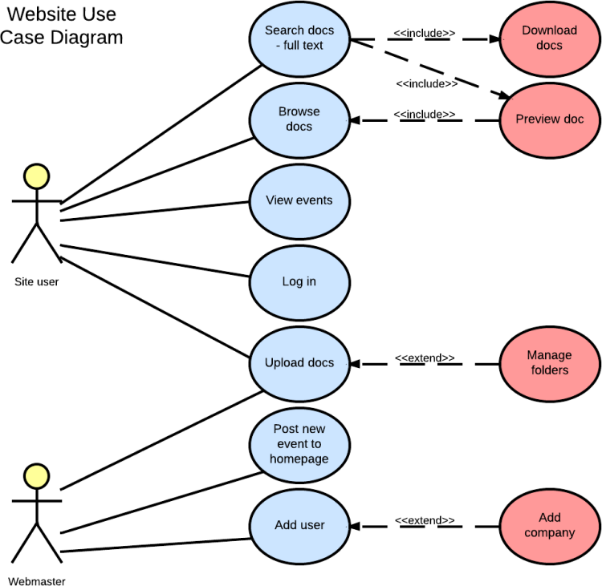
High-Level Use Case Descriptions
A High-Level Use Case Description gives an outline of system capabilities without being too detailed. Each use case contains the actor(s) and short description, a system response. For example, the “Add Inventory” use case includes the Admin, who enters new product details. The system checks and stores the data. The Generate Reports use case allows the Store Manager to request for a list of reports, and the system provide relevant stock details. These descriptions can help to define the functional requirements.
Table 2: High-Level Use Case Descriptions
| Use Case | Actors | Description | System Response |
| Manage Users | Admin | The admin adds, removes, or updates user accounts. | System validates inputs and updates the user database. |
| Add Inventory | Admin, Store Manager | The actor inputs new product details, including name, quantity, and price. | System validates and stores the inventory data. |
| Update Stock | Admin, Store Manager | The actor updates product stock levels based on new shipments or sales. | System updates stock levels and maintains logs. |
| Generate Reports | Admin, Store Manager | The actor requests inventory or sales reports. | System retrieves relevant data and presents reports. |
| Place Orders | Store Manager, Customer | The actor selects products and confirms an order. | System processes the order and updates stock levels. |
| View Product Availability | Customer | The actor checks the availability of products. | System retrieves and displays stock information. |
Expanded Use Case Descriptions
An Expanded Use Case Description describes in detail how a system performs a task. For example, in “Add Inventory,” Admin logs in, chooses the option, fills in product information, and saves them. The system checks and saves the information. If a field is empty, it asks for it.
In the Report Generation section, the Store Manager picks the report option, the type of report, and the system retrieves the required information. If no data is available it will inform the user. These descriptions help to accurately provide system requirements, ensuring that systems are fully functional and can properly report errors (Tetteh, 2024).
Table 3: Use Case 1: Add Inventory
Actor: Admin
| Aspect | Description |
| Preconditions | Admin must be logged in. |
| Steps | 1. Admin selects “Add Inventory”. 2. Enters product details (name, quantity, price). 3. Clicks “Save”. 4. System validates and stores the data. |
| Postconditions | Product is added to the database. |
| Exceptions | If fields are missing, the system prompts for completion. |
Table 4: Use Case 2: Generate Reports
Actor: Store Manager
| Aspect | Description |
| Preconditions | Store Manager must have access rights. |
| Steps | 1. Store Manager selects “Reports”. 2. Chooses a report type (e.g., monthly sales). 3. System fetches data and generates the report. |
| Postconditions | Report is displayed or downloaded. |
| Exceptions | If no data is available, the system notifies the user. |
1.1. Interaction and Behavior Modeling
Sequence Diagram
A Sequence Diagram illustrates how a system works step by step. It helps to see how the various parts of the system relate. First, determine the process to display like “Add Inventory.” Then, list next who or what is affected, the Admin, System, and Database. Then, list each action in sequence. For example, the admin fills in product details, the system verifies them and the database stores them. Use arrow to indicate messages between them. If there is an alert, the system can give a warning. This diagram is helpful because it shows that tasks are carried out in a sequence. It assists developers to build system efficiently.
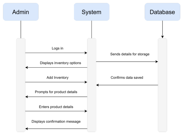
Figure 5: Sequence diagram
Explanation of Developing a Sequence Diagram
Sequence Diagram shows how various parts of a system interact step by step. To create one:
- Identify the use case (e.g. “Add Inventory”)
- List the actors (Admin, System, Database).
- Identify the flow of interactions (Admin enters data, system verifies, data is saved in database).
- Use life lines to represent each actor or system component.
- Draw arrows showing the order of messaging.
- Implement conditions (i.e., system out asks for data when missing).
This diagram clarifies the system flow to developers to makes installation easier.
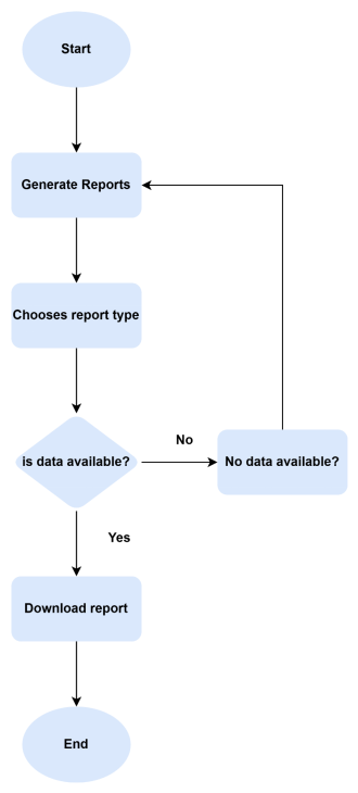
1.1. Activity Diagram
An Activity Diagram illustrates the flow of activities in a process. It describes how a job happens from start to finish. To generate reports, the Store Manager begins this process. The system shows report options. The Store Manager selects a report type, such as monthly sales. The system collects data in and generates the report. If there is data, then the report is displayed or downloaded. If no records are found, the program displays a message. This diagram explains to developers and users how the reports are created. It ensures that all steps are defined and executed correctly.
1.1. Domain and Class Modeling
A Domain Model represents the essential objects within a system. These are called domain objects. They are real-world Objects such as Products, Orders and Reports. A Class Diagram depicts these objects and their relations. Each class has properties (data it contains) and methods (actions it can perform). As, for example, a Product class may have properties such as name and price and methods such as updateStock(). These diagrams assist developers in understanding how data is kept and used within a system. They ensure that all vital items are included and are properly connected.
Table 5: Identified Domain Classes
| Class Name | Attributes | Methods | Description |
| User | userID, name, email, password, role | login(), logout(), updateProfile() | Stores user details and manages authentication. |
| Product | productID, name, category, price, stockQuantity | addProduct(), updateStock(), getDetails() | Represents items available for purchase. |
| Order | orderID, userID, orderDate, totalAmount, status | createOrder(), cancelOrder(), viewOrder() | Manages customer orders. |
| Payment | paymentID, orderID, amount, paymentMethod, status | processPayment(), refundPayment() | Handles transactions. |
| Report | reportID, reportType, generatedDate, generatedBy | generateReport(), viewReport() | Stores system-generated reports. |
Analysis Class Diagram
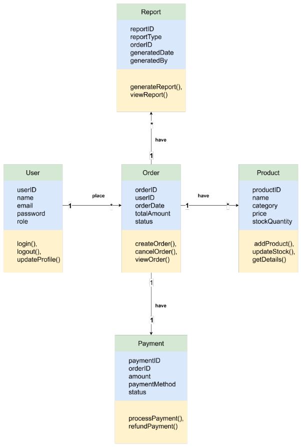
Figure 7: Class diagram
The Analysis Class diagram represents the structure of the system by showing the domain classes and how they are related. Each class has properties (attributes) and behaviors (methods) that describe how they communicate.
- User interacts with Order and Payment.
- Orders consist of Products and Payments.
- Reports are populated from Orders and Products.
This diagram provides a clear object-oriented design that enables easy system implementation.
1. System Design
1.1. Further Development Planning
Agile methodology is the best fit for this project as it offers flexibility and opportunities for ongoing improvement. Agile divides work into small activities, known as sprints. Each sprint has a short duration, typically one to four weeks. After each sprint, the team verifies progress and adjusts as necessary. This technique helps you catch problems early and resolve them fast. Further planning will include setting up specific sprint objectives, delegating tasks, and establishing due dates. Regular meetings will ensure good progress. Feedback from users and stakeholders will be obtained regularly to enhance the system incrementally (Madamidola et al., 2024).
1.2. Architectural and Design Decisions
System Architecture
The system will use a three tier system architecture that consists of presentation layer, application layer, database layer. The presentation layer is the user interface through which users engage with the system. It will be developed with latest web tech for seamless browsing experience. Application layer has business logic and process user requests. It will utilize a backend framework to operate operations effectively. The database layer will safely store and retrieve data, providing reliability and fast accessibility. The architecture provides scalability, security and maintainability of the system.
Design Patterns
Different design patterns will be used, which ensures a structured, and maintainable system. The Model-View-Controller (MVC) pattern will isolate data, business logic, and user interface so that development and in particular enhancements are easier. The Singleton pattern will be used to handle database connections efficiently, such that only one instance of database connection is present. The Factory pattern will help to dynamically create objects without knowing the actual classes. This will make code reusable & flexible. These patterns will help create a well-organized and stable system, simplifying future updates and changes (Roosevelt et al., 2024).
1.3. Development Plan
Tools, Resources, and Programming Platforms
The system will be created with the use of up to date software tools and platforms. React.js will be used for Front End development which provide the dynamic and responsive user interface. Backend will be developed with Node.js and Express.js for its speed and scalability server-side logic. SQLite shall serve as a database to store the user and system data effectively. Git and GitHub will be used for version control to track changes and work collaboratively on the development. Draw.io is used for system modeling which includes use case and activity diagrams. The development environment will be consists of Visual Studio Code and Postman for API testing (Kuhrmann et al., 2021).
Priority Order of Features
- User Authentication & Authorization – Secure login and user roles.
- Core System Functions – Development of core capabilities like report generation, data administration, and workflow automation.
- Database Integration – Keeping and fetching necessary system information.
- User Interface Development – Creating a user-friendly experience.
- Notification System – Alerts & Notifications to Users.
- Security Enhancements – Adding encryption and access controls.
- Performance Optimization – Improving system speed and efficiency.
- Testing & Debugging – Making sure all features are working correctly.
1.4. Testing Plan
Testing is an essential process to ensure that the system works as intended and meets the expectations of the users. There will be three main testing approaches:
- Unit Testing – This will focus on testing the different components within the system, like functions, module, and database queries. Developers will use automated testing tools such as Jest for JavaScript code and Postman for API test.
- System Testing – This will verify that all components are working together as intended. The entire system will be tested for operation, security and performance to ensure it meets design specifications.
- User Acceptance Testing (UAT) – End users will manually use the system to verify that the solution fulfils their requirements. Feedback will be collected and any required adjustments will be made before launch.
1.5. Maintenance Plan
The system will require periodic maintenance after deployment to prevent disruption. The maintenance plan includes:
- Bug Fixing & Updates – Regular checks will solve software bugs in time. System updates will be applied to improve system operation and security.
- Performance Tuning – The system will be assessed for speed and efficiency and tuning will be done as needed.
- User Support & Training – A dedicated support team will aid users with system problems. Training documentation will be accessible for users to learn how to use the system.
- Security Updates – Regular security patches are applied to mitigate the risk of cyber threats.
- Scalability & Features Improvement – As the user base grows, then new features will be introduced and system optimization will be performed for better performance.
- This structured approach guarantees that the system stays reliable, secure and useful once deployed (Govil et al., 2022).
1.6. UI/UX Design and Prototypes
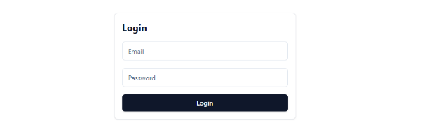
- Login Page – This page allows users to enter their credentials to access the system securely. It ensures only authorized users can log in.
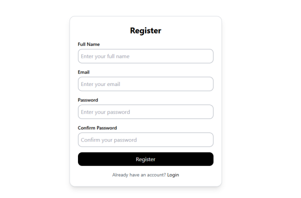
User Registration Page – New users can fill out a form to create an account. It collects necessary details for authentication
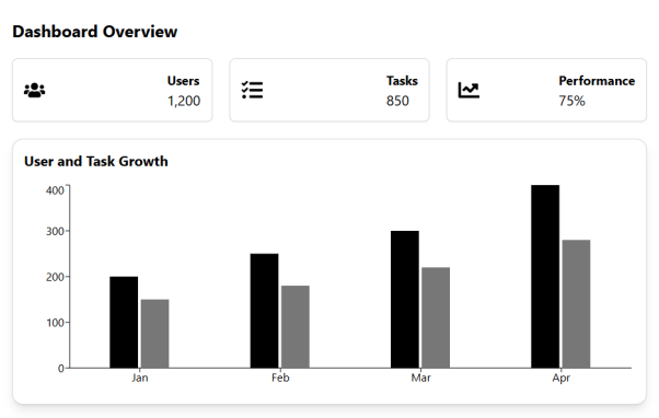
Dashboard – The dashboard gives an overview of system activities and important updates. It provides quick access to key features.
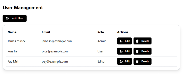
User Management Page – Admin interface for managing users. Admins can view, modify, or delete a user account. This page is helpful to manage system users efficiently.
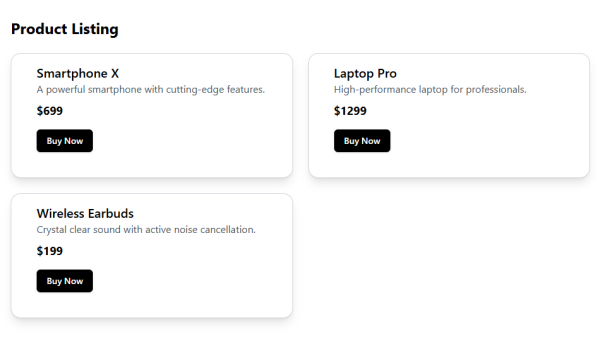
Product Listing Page – This page shows available products & services. Users can search and select items of interest.
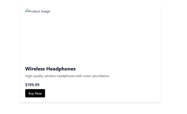
Product Details Page – Users can obtain detailed information about a chosen product or service. This includes details, with photos and the prices.
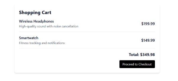
Shopping Cart – Shoppers can browse and edit chosen items for purchase. It allows quantities to be added or removed.
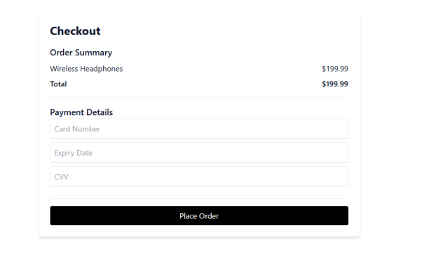
Checkout Page – This page displays all order and payment information. Users confirm the purchase and enter payment.
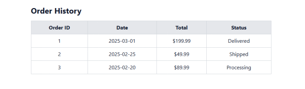
Order History – Users can view history of their transactions and orders. It helps monitor purchases and download invoices.
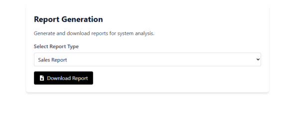
Report Generation Page – The system provides reports on different activities. Users can download report for analysis.
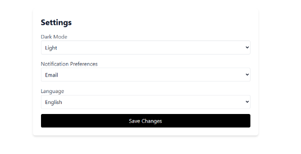
Settings Page – Users can modify preferences like notifications, account settings. It helps personalize the system.
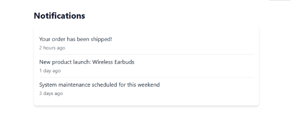
Notifications Page – User gets notification for updates, messages & system updates. It helps them stay up to date on issues.
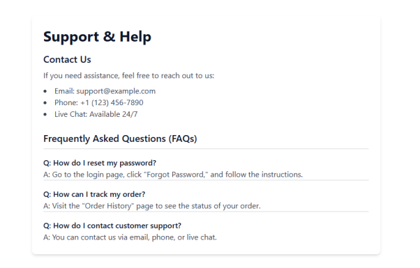
Support/Help Page – Users can find support FAQs or get help from support. It resolves issues and answers your questions.
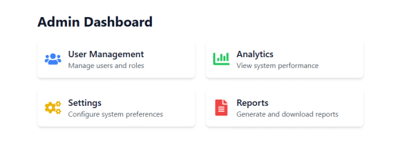
Admin Dashboard – This offers administration level controls for the system administrator. Admins manage Users, Settings and Reports.
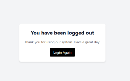
Logout Page – Users are securely logged out of the system. It blocks unauthorized access after the session.
Conclusion
The Inventory Management System (IMS) was developed and built with efficiency, simplicity and scalability in mind. The process of design was thorough, choosing the technologies right, and developing a simple user interface. The system was designed to be modular, so that different parts, like product management, user management and order tracking, were able to work together without any issues. The frontend was kept as simple and responsive as possible, giving a seamless interaction experience to users. During the development, we focused on a clean code, clear navigation and a visually nice layout to improve usability (Rasheed et al., 2021).
Several lessons were noted during the project. One of the big lessons was the need for planning before coding. Good documentation and clear processes ensured clarity from development start to finish. Another valuable lesson learned was consistency of the user interface; it made the user experience better overall. Besides, testing at each stage allowed us to catch and fix this minor problem before it turned into a major one. The project also highlighted the necessity for adaptability, as constant adjustments and improvements were made based on new learnings (Moyano et al., 2022).
There is still room for future upgrade to the IMS. Features like real-time analytics, AI-driven inventory forecasting, and tighter integration with external systems can be added to further enhance functionality. Security functions will need to be improved and the system needs to be optimized to allow long term scalability. Future updates may prioritize improvements to automation and the capability to adjust the system to meet business responsiveness (Mishra, & Alzoubi, 2023).
References
Adzgauskaite, M., Tam, C. and Martins, R., 2025. What helps Agile remote teams to be successful in developing software? Empirical evidence. Information and Software Technology, 177, p.107593.
Aratchige, R., Manujaya, K. and Weerasinghe, P., 2024. An Overview of Structural Design Patterns in Object-Oriented Software Engineering. Sofware Modeling, pp.1-3.
Day, M.Y., 2025. Introduction to software engineering.
Govil, N. and Sharma, A., 2022. Validation of agile methodology as ideal software development process using Fuzzy-TOPSIS method. Advances in Engineering Software, 168, p.103125.
Kuhrmann, M., Tell, P., Hebig, R., Klünder, J., Münch, J., Linssen, O., Pfahl, D., Felderer, M., Prause, C.R., MacDonell, S.G. and Nakatumba-Nabende, J., 2021. What makes agile software development agile?. IEEE transactions on software engineering, 48(9), pp.3523-3539.
Lenberg, P., Feldt, R., Gren, L., Wallgren Tengberg, L.G., Tidefors, I. and Graziotin, D., 2024. Qualitative software engineering research: Reflections and guidelines. Journal of Software: Evolution and Process, 36(6), p.e2607.
Madamidola, O.A., Daramola, O.A., Akintola, K.G. and Adeboje, O.T., 2024. A Review of existing inventory management systems. International Journal of Research in Engineering and Science (IJRES), 12(9), pp.40-50.
Mishra, A. and Alzoubi, Y.I., 2023. Structured software development versus agile software development: a comparative analysis. International Journal of System Assurance Engineering and Management, 14(4), pp.1504-1522.
Moyano, C.G., Pufahl, L., Weber, I. and Mendling, J., 2022. Uses of business process modeling in agile software development projects. Information and Software Technology, 152, p.107028.
Rasheed, A., Zafar, B., Shehryar, T., Aslam, N.A., Sajid, M., Ali, N., Dar, S.H. and Khalid, S., 2021. Requirement engineering challenges in agile software development. Mathematical Problems in Engineering, 2021(1), p.6696695.
Roosevelt, S.C., Veemaraj, E. and Kirubakaran, S., 2024, July. Real Time Stock Inventory Management System. In 2024 8th International Conference on Inventive Systems and Control (ICISC) (pp. 156-162). IEEE.
Tetteh, S.G., 2024. Empirical Study of Agile Software Development Methodologies: A Comparative Analysis. Asian Journal of Research in Computer Science, 17(5), pp.30-42.